Continuous analyte sensors and methods of making same

a technology of analyte sensors and sensors, applied in the field of continuous analyte sensors, can solve the problems of increasing glucose concentration and property and achieve the effect of minimizing variations among the sensors produced and reducing production costs

Inactive Publication Date: 2011-02-03
DEXCOM
View PDF105 Cites 492 Cited by
  • Summary
  • Abstract
  • Description
  • Claims
  • Application Information

AI Technical Summary

Benefits of technology

The patent text is about a process and system that can make continuous analyte sensors more efficiently and consistent. This will save money and reduce the variation between sensors.

Problems solved by technology

The technical problem addressed in this patent text is the need for a more cost-effective and consistent method of manufacturing continuous electrochemical analyte sensors that can measure blood glucose concentrations in individuals with diabetes. The current batch processes used for sensor production may not be suitable for large-scale manufacturing and can result in variations in sensor properties.

Method used


Image

  • Continuous analyte sensors and methods of making same
  • Continuous analyte sensors and methods of making same
  • Continuous analyte sensors and methods of making same

Examples


Embodiment Construction

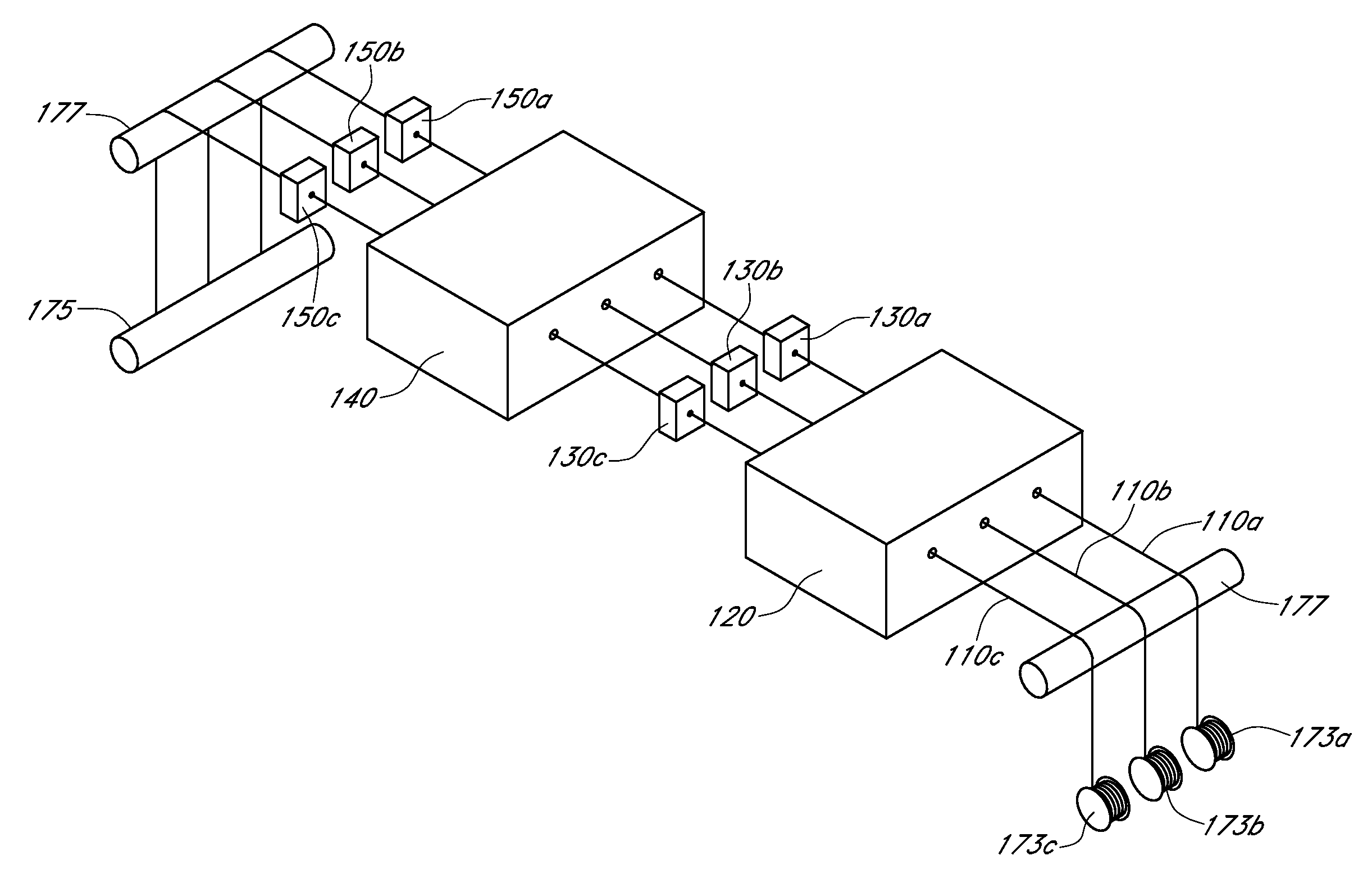
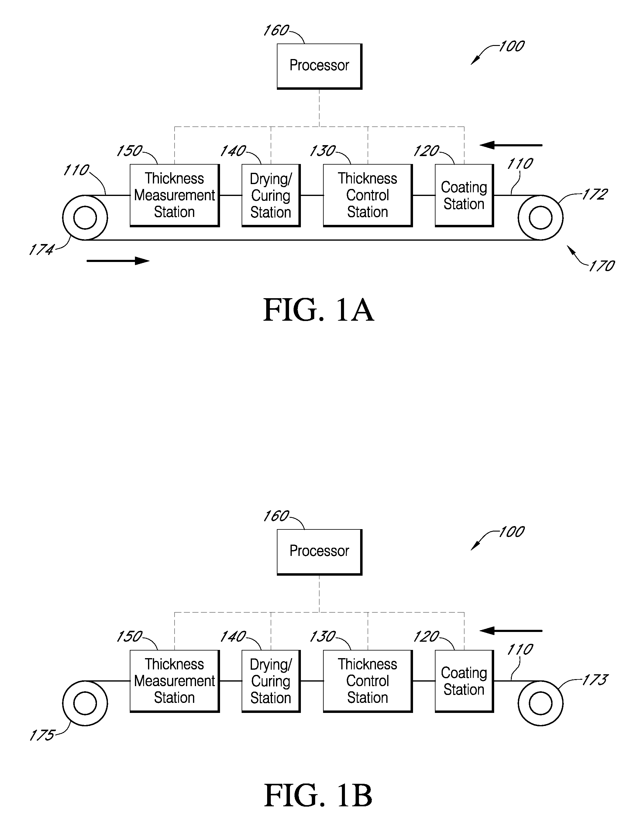
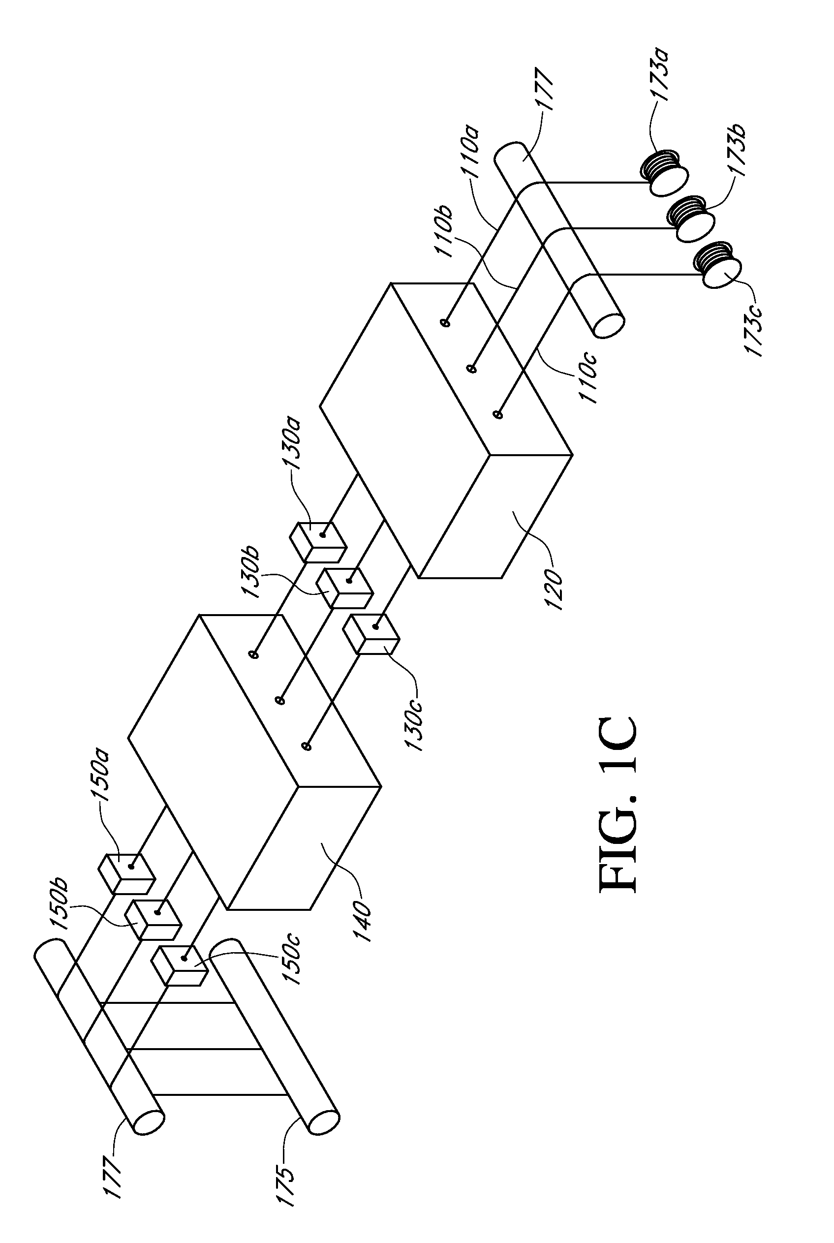
[0057]The following description and examples describe in detail some exemplary embodiments of systems and methods for manufacturing continuous analyte sensors. It should be understood that there are numerous variations and modifications of the systems, methods, and devices described herein that are encompassed by the present invention. Accordingly, the description of a certain exemplary embodiment should not be deemed to limit the scope of the present invention.

DEFINITIONS

[0058]In order to facilitate an understanding of the devices and methods described herein, a number of terms are defined below.

[0059]The term “analyte,” as used herein, is a broad term, and is to be given its ordinary and customary meaning to a person of ordinary skill in the art (and is not to be limited to a special or customized meaning), and refers without limitation to a substance or chemical constituent in a biological fluid (for example, blood, interstitial fluid, cerebral spinal fluid, lymph fluid, urine, s...


PUM

PropertyMeasurementUnit
Thicknessaaaaaaaaaa
Thicknessaaaaaaaaaa
Lengthaaaaaaaaaa

Abstract

Described here are embodiments of processes and systems for the continuous manufacturing of implantable continuous analyte sensors. In some embodiments, a method is provided for sequentially advancing an elongated conductive body through a plurality of stations, each configured to treat the elongated conductive body. In some of these embodiments, one or more of the stations is configured to coat the elongated conductive body using a meniscus coating process, whereby a solution formed of a polymer and a solvent is prepared, the solution is continuously circulated to provide a meniscus on a top portion of a vessel holding the solution, and the elongated conductive body is advanced through the meniscus. The method may also comprise the step of removing excess coating material from the elongated conductive body by advancing the elongated conductive body through a die orifice. For example, a provided elongated conductive body 510 is advanced through a pre-coating treatment station 520, through a coating station 530, through a thickness control station 540, through a drying or curing station 550, through a thickness measurement station 560, and through a post-coating treatment station 570.

Description


Claims


Application Information

Patent Timeline
Owner DEXCOM
Why Eureka
Try Eureka