Exhaust gas purification apparatus

a technology of exhaust gas and purification apparatus, which is applied in the direction of exhaust treatment electric control, separation process, machines/engines, etc., can solve the problems of deterioration of the efficiency of removing no/sub>x relative to the use of urea water

Inactive Publication Date: 2011-02-10
TOYOTA IND CORP
View PDF0 Cites 16 Cited by
  • Summary
  • Abstract
  • Description
  • Claims
  • Application Information

AI Technical Summary

Problems solved by technology

However, a distance that is enough to ensure the reaction time is not provided between the urea water injector and the DPF having the urea SCR catalyst supported therein in the above-described exhaust gas aftertreatment device.
Consequently, efficiency of removing NOx relative to the use of urea water deteriorates.

Method used


Image

  • Exhaust gas purification apparatus
  • Exhaust gas purification apparatus
  • Exhaust gas purification apparatus

Examples


Embodiment Construction

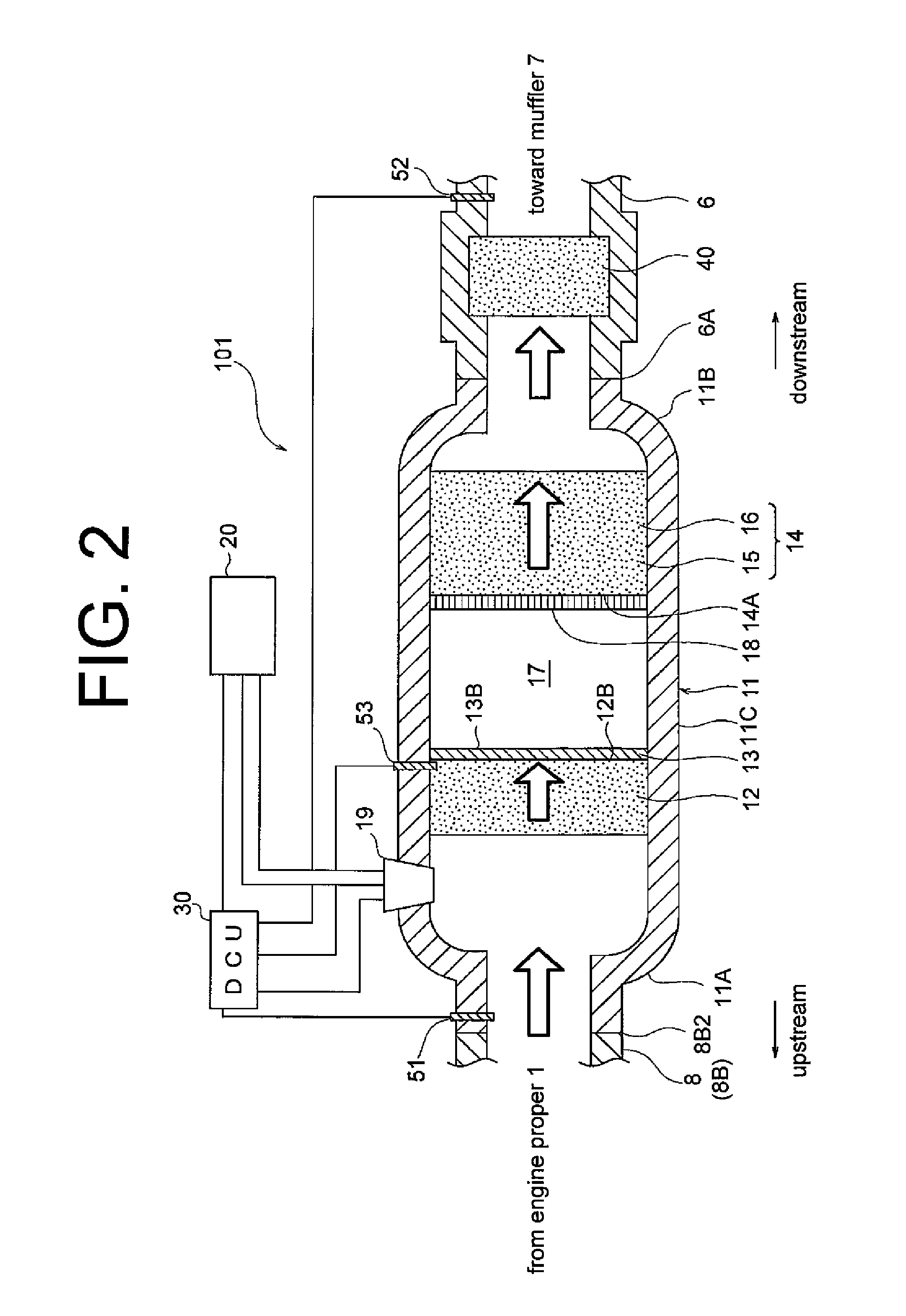
[0016]The following will describe the embodiments of the present invention with reference to the accompanying drawings. An exhaust gas purification apparatus 101 according to the first embodiment of the present invention and its peripheral equipment will be described with reference to FIGS. 1 and 2. In the following embodiments, the exhaust gas purification apparatus is used for a diesel engine for a vehicle.

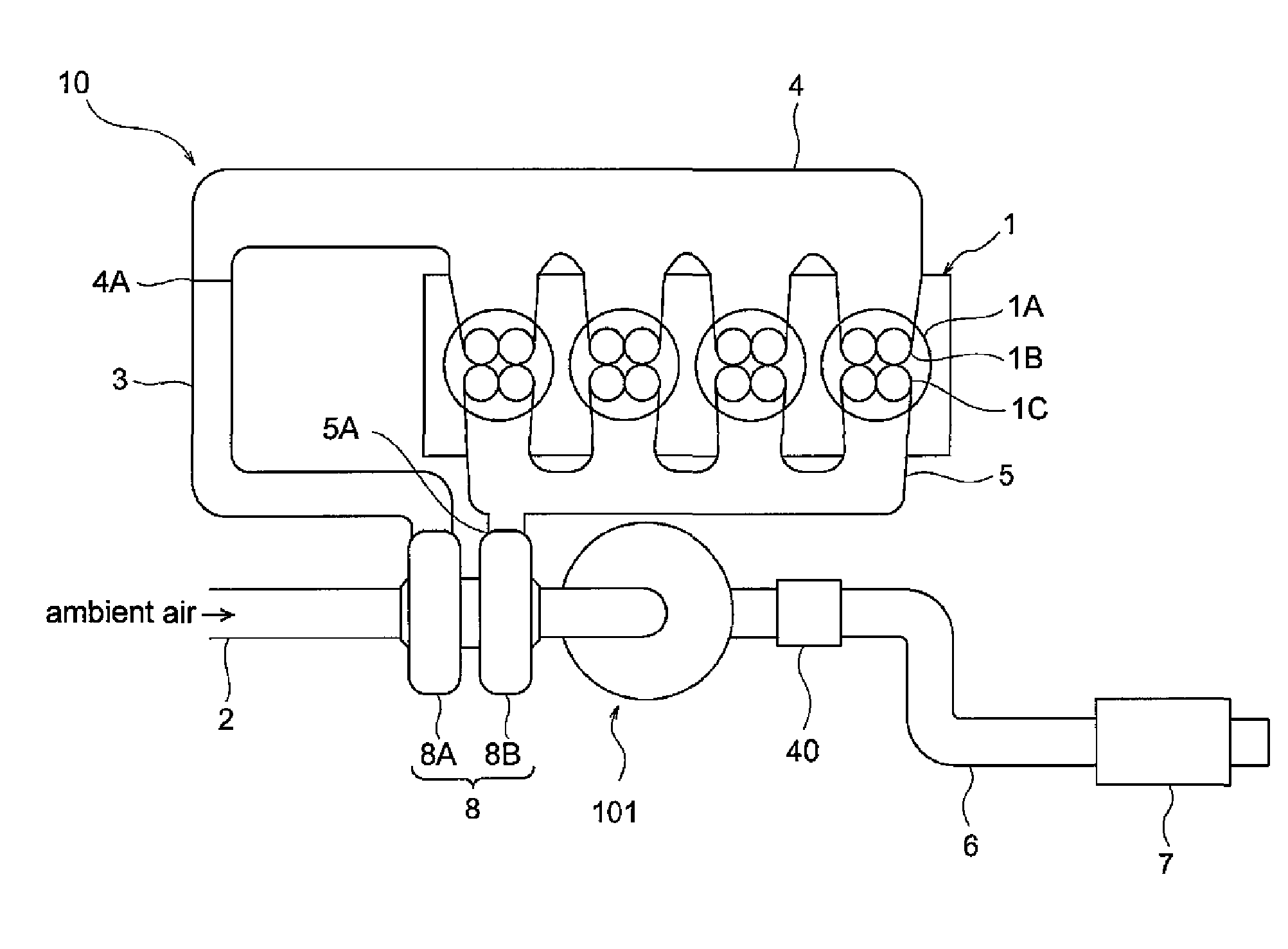
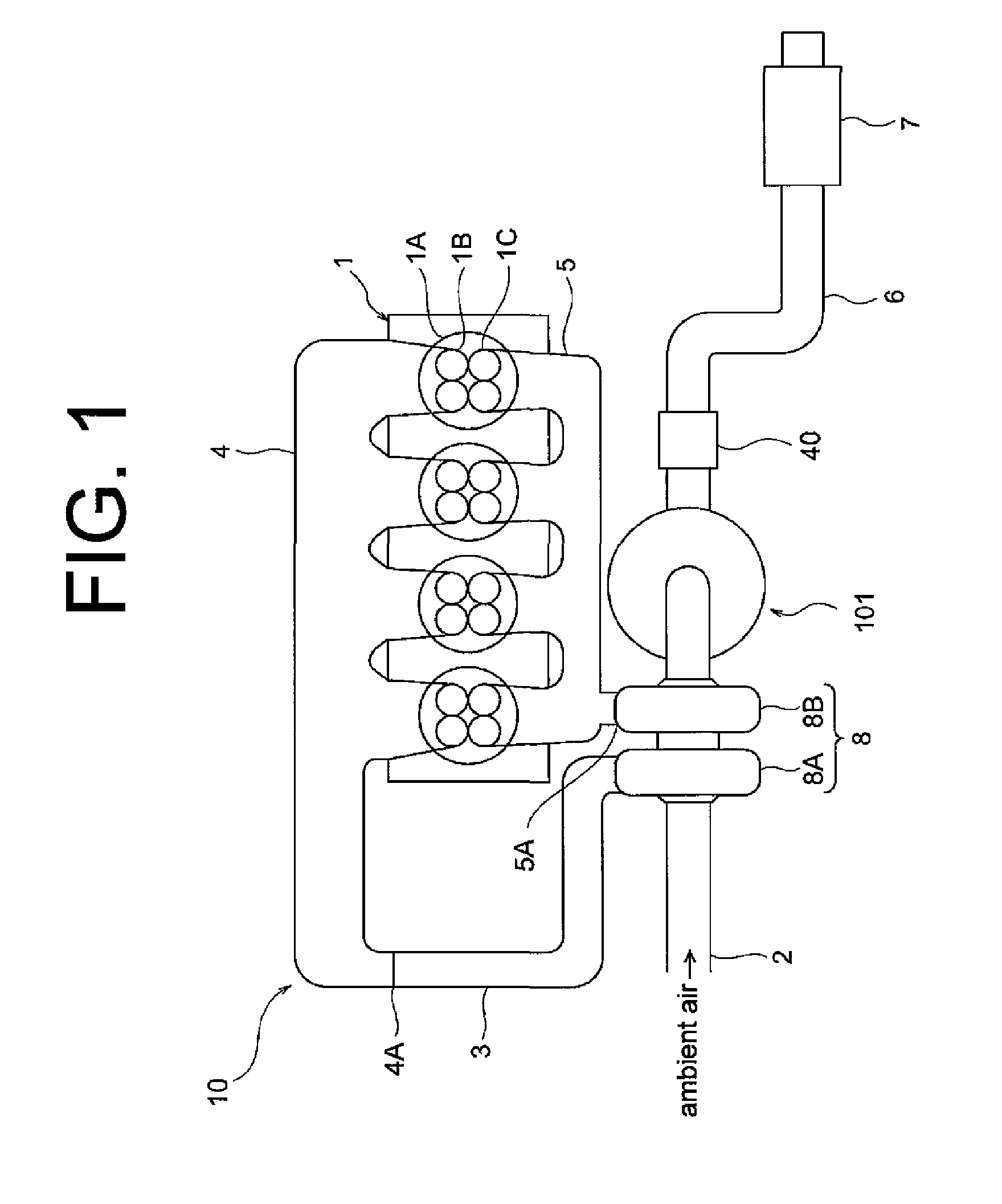
[0017]Referring to FIG. 1 showing the exhaust gas purification apparatus 101 and its peripheral equipment in schematic view, an engine proper 1 has a plurality of engine cylinders 1A each having a plurality of intake ports 1B and a plurality of exhaust ports 1C. An intake manifold 4 is connected to the intake ports 1B of the engine cylinders 1A for distributing intake air into the respective engine cylinders 1A. The intake manifold 4 has an inlet 4A through which air is drawn in. An engine intake pipe 3 has two opposite ends one of which is connected to the inlet 4A of the intak...


PUM

PropertyMeasurementUnit
temperatureaaaaaaaaaa

Abstract

The exhaust gas purification apparatus includes an oxidation catalyst, an ammonia adsorption portion, a selective catalytic reduction catalyst and a urea water supply device. The oxidation catalyst is provided in a passage through which exhaust gas flows. The ammonia adsorption portion is located in the passage downstream of the oxidation catalyst with respect to the flow of the exhaust gas and operable to adsorb ammonia. The selective catalytic reduction catalyst is located in the passage downstream of the ammonia adsorption portion. The urea water supply device is provided for supplying urea water to the passage upstream of the selective catalytic reduction catalyst.

Description

BACKGROUND OF THE INVENTION[0001]The present invention relates to an exhaust gas purification apparatus and more particularly to an exhaust gas purification apparatus that purifies exhaust gas by removing nitrogen oxides (NOx) contained in the exhaust gas of a diesel engine with the aid of a urea selective catalytic reduction (SCR) catalyst.[0002]A urea SCR system has been developed to purify exhaust gas by removing NOx contained in the exhaust gas of a diesel engine. The urea SCR system uses an SCR catalyst as a selective reduction catalyst to convert NOx into nitrogen (N2) and water (H2O) by the chemical reaction between NOx and ammonia (NH3) produced by hydrolyzing urea water.[0003]The SCR catalyst of the urea SCR system is provided in the exhaust gas passage formed between an engine and a muffler that is located downstream of the engine with respect to the flow of exhaust gas. An oxidation catalyst is provided in the exhaust gas passage at a position upstream of the SCR catalyst...

Claims


Application Information

Patent Timeline
Patent Type & Authority Applications(United States)
IPC IPC(8): F01N3/035B01D50/00
CPCF01N3/0807F01N3/105F01N3/2066F01N9/00F01N2560/026F01N13/009F01N2570/14F01N2610/02Y02T10/47Y02T10/24F01N13/0093F01N2560/06Y02T10/12Y02T10/40Y02A50/20
Inventor KATO, YOSHIFUMI
Owner TOYOTA IND CORP
Why Eureka
Try Eureka