Flow management system for hydraulic work machine

a hydraulic work machine and flow management technology, applied in the direction of fluid couplings, servomotors, couplings, etc., can solve the problems of increasing the likelihood of cavitation and associated pitting in the hydraulic pump and associated control valve, the physical size and weight of the accumulator is undetected, and the air bubbles cannot escape from the accumulator, so as to increase the actuator's dynamic, reduce energy loss, and prolong the life of the shaft seal

Active Publication Date: 2011-02-10
PARKER INTANGIBLES LLC
View PDF11 Cites 139 Cited by
  • Summary
  • Abstract
  • Description
  • Claims
  • Application Information

AI Technical Summary

Benefits of technology

[0014]The invention has particular application to working machines utilizing electro-hydrostatic actuation with unbalanced cylinders that desirably have a boosted inlet hydraulic fluid supply capable of maintaining a suitably elevated pressure at the actuation system pump inlet under all dynamic activities demanded by the working machine. In this way, aeration, cavitation and associated destructive pitting of component parts which may result from exposure to a vacuum or sharp and rapid pressure changes, can be substantially reduced if not eliminated.
[0061]Optionally or additionally, current to the boost pump motor may be controlled as a function of the commanded speed of the bidirectional pump motor, thereby to increase boost system pressure for higher operating speeds of the bidirectional pump motor.

Problems solved by technology

This distance increases the likelihood of cavitation and associated pitting occurring in the hydraulic pumps and associated control valves as the hydraulic fluid is exposed to sharp and rapid pressure drops resulting from the demands of highly responsive actuators.
As a result, the physical size and weight of the accumulator is undesirably large.
Also, since some of the hydraulic fluid contained in the accumulator is not circulated to and from a tank or reservoir that is open to the atmosphere, entrained air bubbles are not allowed to escape from the accumulator.
This problem may be compounded if gas leakage should occur across the accumulator bladder.
Also, gas charged accumulators require added maintenance due to the need for a gas charging means.
There is also the threat of external nuisance gas and hydraulic fluid leakage during storage since at least a part of the system remains under pressure at all times.
Much of the output of the charge pump is dumped across a relief valve 44, with consequent heat generation and energy loss.
The flow management and temperature control systems heretofore employed have been inefficient, expensive and / or complicated.

Method used


Image

  • Flow management system for hydraulic work machine
  • Flow management system for hydraulic work machine
  • Flow management system for hydraulic work machine

Examples


Embodiment Construction

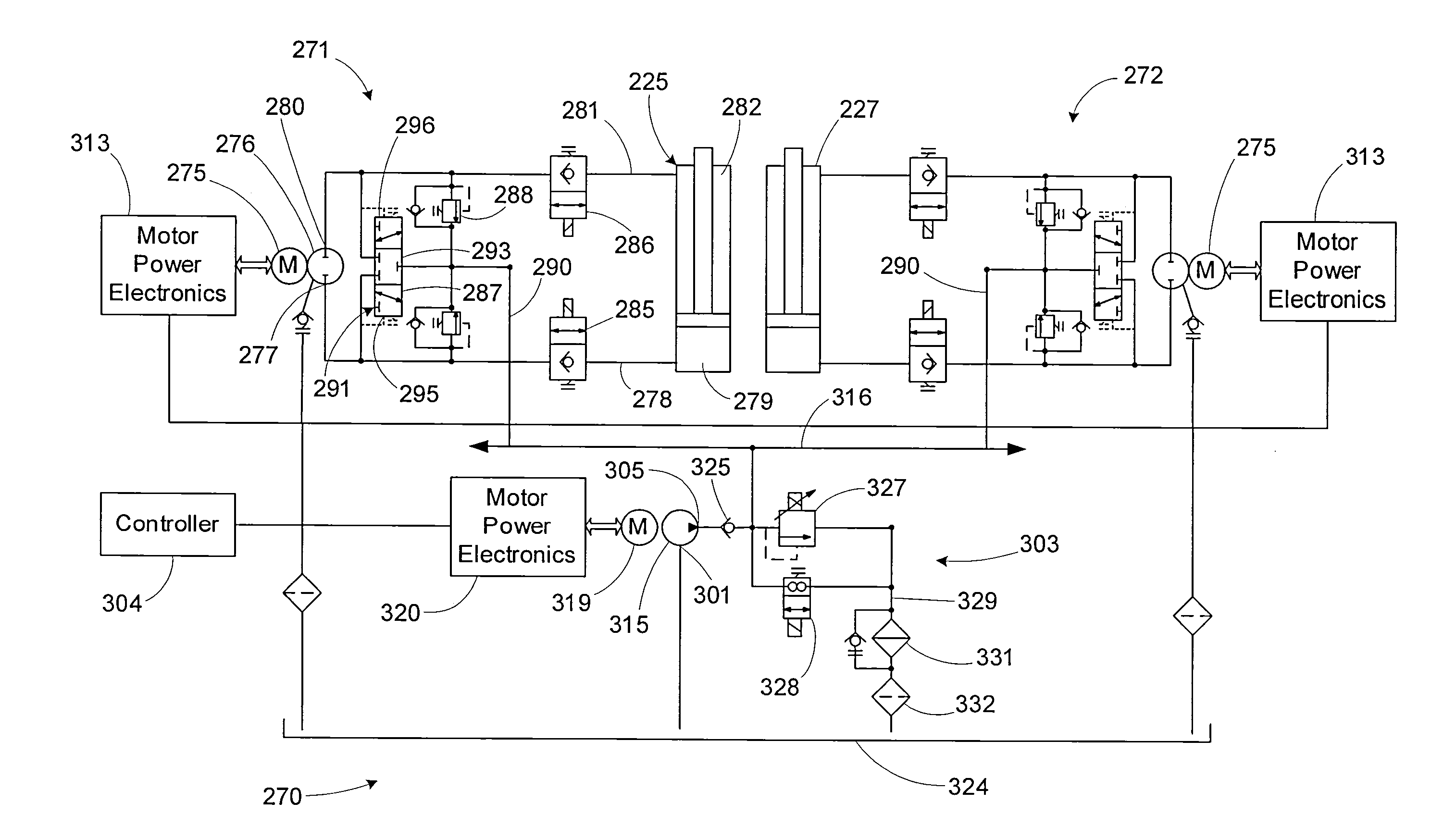
[0077]Referring now in detail to the drawings and initially to FIG. 4, an exemplary flow management system according to the invention is depicted at 100. The system 100 comprises at least one actuator system (two actuator systems 101 and 102 are shown by way of example, but the number may be varied for any given application), a boost system 103 for accepting or supplying fluid from or to the one or more actuator systems, and a controller 104.

[0078]Each actuator system 101, 102 includes a bi-directional pump 107 operable in one direction for supplying pressurized fluid from one inlet / outlet port 108 to a hydraulic actuator (not shown) for operating the actuator in one direction, and operable in a second direction opposite the first direction for supplying pressurized fluid from another inlet / outlet port 109 to the hydraulic actuator for operating the actuator in a direction opposite the first direction. Each actuator system also includes an electric bi-directional pump drive 111 for ...


PUM


Abstract

A flow management system capable of providing adjustable hydraulic fluid flow or pressure at a common line to supply bidirectional pumps in electro-hydrostatic actuation systems and conditioning re-circulated hydraulic fluid. The system enables flow sharing between multiple actuation systems and minimization of energy consumption by a power-on-demand approach and / or electrical energy regeneration while eliminating the need for an accumulator. The system has particular application to electro-hydrostatic actuation systems that typically include bi-directional electric motor driven pumps and unbalanced hydraulic actuators connected within closed circuits to provide work output against external loads and reversely recover energy from externally applied loads.

Description

RELATED APPLICATION DATA[0001]This application claims priority of U.S. Provisional Application No. 61 / 028,004 filed Feb. 12, 2008, which is hereby incorporated herein by reference in its entirety.FIELD OF THE INVENTION[0002]The invention relates generally to hydraulic actuation systems for extending and retracting at least one unbalanced hydraulic cylinder in a work machine, such as but not limited to hydraulic excavators, wheel loaders, loading shovels, backhoe shovels, mining equipment, industrial machinery and the like, having one or more actuated components such as lifting and / or tilting arms, booms, buckets, steering and turning functions, traveling means, etc. The invention has particular application to closed circuit electro-hydrostatic actuation systems requiring elevated inlet hydraulic fluid pressure and improved hydraulic fluid conditioning.BACKGROUND OF THE INVENTION[0003]In a typical unbalanced (differential) hydraulic cylinder, the cross-sectional area of the chamber o...

Claims


Application Information

Patent Timeline
Patent Type & Authority Applications(United States)
IPC IPC(8): F15B11/17F15B11/00F15B21/08
CPCE02F9/2217F15B2211/7053E02F9/2296F15B7/006F15B21/08F15B2211/20515F15B2211/20538F15B2211/20561F15B2211/20569F15B2211/20584F15B2211/50527F15B2211/613F15B2211/62F15B2211/633F15B2211/6346E02F9/2242F15B2211/30515
Inventor PERSSON, BENGT-GORANVANDERLAAN, DALEKASPER, LEW
Owner PARKER INTANGIBLES LLC
Why Eureka
Try Eureka