
Start-up procedure for refrigerant systems having microchemical consensor and reheat cycle

a technology of microchemical consensor and reheat cycle, which is applied in the direction of lighting and heating apparatus, domestic cooling apparatus, heating types, etc., can solve the problems of high discharge operating pressure, instantaneous pressure spike, and microchannel heat exchangers that are more susceptible to refrigerant pressure variations, etc., to achieve the effect of higher operating speed of variable speed compressors

Inactive Publication Date: 2011-02-10
CARRIER CORP
View PDF17 Cites 15 Cited by
  • Summary
  • Abstract
  • Description
  • Claims
  • Application Information

AI Technical Summary

Benefits of technology

[0009]These and other features of the present invention can be best understood from the following specification and drawings, the following of which is a brief description.

Problems solved by technology

Due to low internal volume, microchannel heat exchangers are more susceptible to refrigerant pressure variations due to instantaneous changes in refrigerant flow throughout the refrigerant circuit.
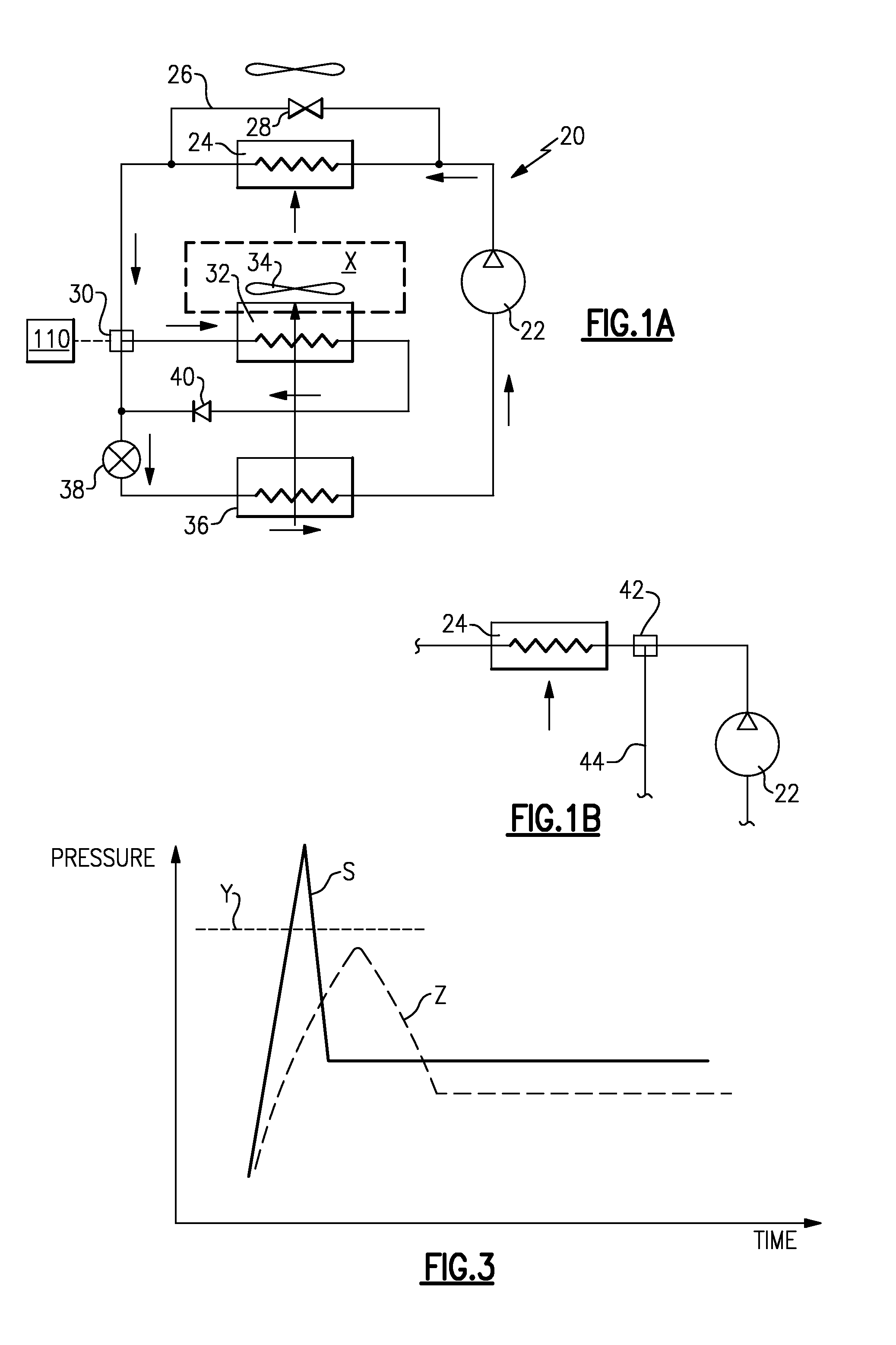
Microchannel heat exchangers are also very sensitive to refrigerant charge amounts, with even a small amount of extra refrigerant charge in the system leading to higher than desirable discharge operating pressures and instantaneous pressure spikes.
These problems are especially pronounced during start-ups.
Nuisance interruptions of the refrigerant system operation can be a result of emergency shutdown by control software on a high pressure alarm or by mechanical safety, such as a high pressure switch, leading to complete inability to operate the refrigerant system, if a discharge pressure spike exceeded predetermined allowable safe limit (typically for a preset number of times).
This consequently would results in a failure to keep a climate-controlled environment within desirable temperature and humidity ranges, leading to occupant discomfort and liability claims.
Under certain circumstances, repeated starts and shutdowns in short periods of time can potentially lead to a compressor failure.

Method used


Image

  • Start-up procedure for refrigerant systems having microchemical consensor and reheat cycle
  • Start-up procedure for refrigerant systems having microchemical consensor and reheat cycle
  • Start-up procedure for refrigerant systems having microchemical consensor and reheat cycle

Examples


Embodiment Construction

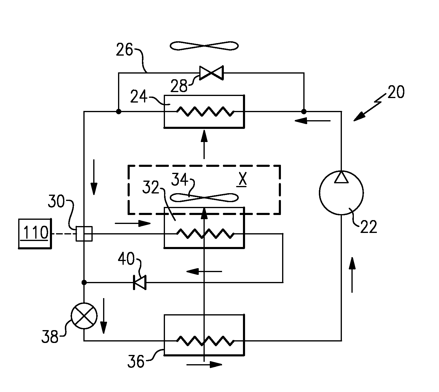
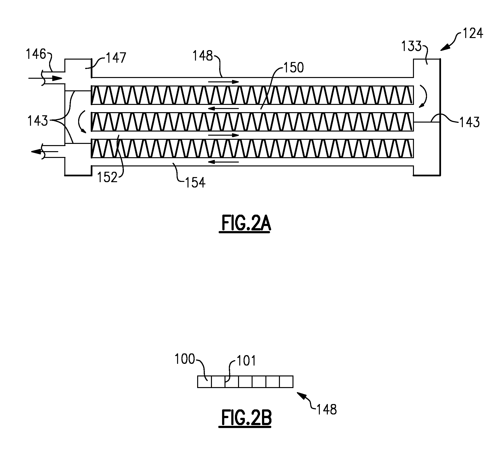
[0015]A refrigerant system 20 is illustrated in FIG. 1A and includes a compressor 22 delivering refrigerant into a discharge line heading to a condenser 24. The condenser 24 is a parallel flow heat exchanger, and in one disclosed embodiment is a microchannel or minichannel heat exchanger. As mentioned above, these terms are used interchangeably here.

[0016]Heat is transferred in the condenser 24 from the refrigerant to a secondary fluid, such as ambient air. The high pressure, desuperheated, condensed and typically subcooled, refrigerant passes from the condenser 24 into an expansion device 38, where it is expanded to a lower pressure and temperature. Downstream of the expansion device 38, refrigerant flows through an evaporator 36 and back to the compressor 22. As known, the heat exchanger 24 operates as a condenser in subcritical applications and as a gas cooler in transcritical applications. Nevertheless, although both applications are within the scope of the invention, the heat e...


PUM


Abstract

A refrigerant system has a condenser of microchannel design and construction and includes a reheat cycle. The reheat cycle includes a refrigerant flow control device, such as a three-way valve, for selectively routing at least a portion of refrigerant through a reheat heat exchanger from a location between a compressor and expansion device. A control for the refrigerant system selectively actuates this refrigerant flow control device to route at least a portion of refrigerant through the reheat heat exchanger at system start-up.

Description

RELATED APPLICATIONS[0001]This application claims priority to U.S. Provisional Patent Application No. 61 / 061,142, which was filed Jun. 13, 2008.BACKGROUND OF THE INVENTION[0002]Refrigerant systems utilize a refrigerant to condition a secondary fluid, such as air, delivered to a climate-controlled space. In a basic refrigerant system, the refrigerant is compressed in a compressor, and flows downstream to a condenser in a subcritical refrigerant cycle or to a gas cooler in a transcritical refrigerant cycle, where heat is typically rejected from the refrigerant to ambient environment, during heat transfer interaction with this ambient environment. Then refrigerant flows through an expansion device, where it is expanded to a lower pressure and temperature, and to an evaporator, where during heat transfer interaction with a secondary fluid (e.g., indoor air), the refrigerant is evaporated and typically superheated, while cooling and often dehumidifying this secondary fluid.[0003]In recen...

Claims


Application Information

Patent Timeline
IPC IPC(8): F25B41/00
CPCF24F3/153F25B2400/075F28F2260/02F25B2600/2521F28D1/05391F25B2500/26
Inventor TARAS, MICHAEL F.FRASER, ERIC B.
Owner CARRIER CORP
Learn More