
Sputtering target apparatus

a target and apparatus technology, applied in the direction of electrolysis components, vacuum evaporation coatings, coatings, etc., can solve the problems of increasing the length of the target, and affecting the quality of the targ

Active Publication Date: 2011-02-10
SAMSUNG DISPLAY CO LTD
View PDF4 Cites 23 Cited by
  • Summary
  • Abstract
  • Description
  • Claims
  • Application Information

AI Technical Summary

Benefits of technology

[0010]Exemplary embodiments of the present invention provide a sputtering target apparatus that

Problems solved by technology

However, as a target length increases, a method of manufacturing a target assembly has posed a limitation.
That is, if a target is formed of a brittle ceramic oxide, an increase in the length of the target may cause damage to a ceramic material in the target.
However, the conventional target assembly has a drawback in that electrical characteristics of a thin film formed by sputtering are found to vary across the thin film due to uneven distribution of materials of the bonding agent within the thin film.

Method used


Image

  • Sputtering target apparatus
  • Sputtering target apparatus
  • Sputtering target apparatus

Examples


Embodiment Construction

[0029]The invention is described more fully hereinafter with reference to the accompanying drawings, in which embodiments of the invention are shown. This invention may, however, be embodied in many different forms and should not be construed as limited to the embodiments set forth herein. Rather, these embodiments are provided so that this disclosure is thorough and will fully convey the scope of the invention to those skilled in the art. Like reference numerals in the drawings refer to like elements throughout the specification. In the drawings, the size and relative sizes of layers and regions may be exaggerated for clarity.

[0030]It will be understood that when an element or layer is referred to as being “on” or “connected to” another element or layer, it can be directly on or directly connected to the other element or layer, or intervening elements or layers may be present. In contrast, when an element is referred to as being “directly on” or “directly connected to” another elem...


PUM

PropertyMeasurementUnit
Shapeaaaaaaaaaa
Circumferenceaaaaaaaaaa

Abstract

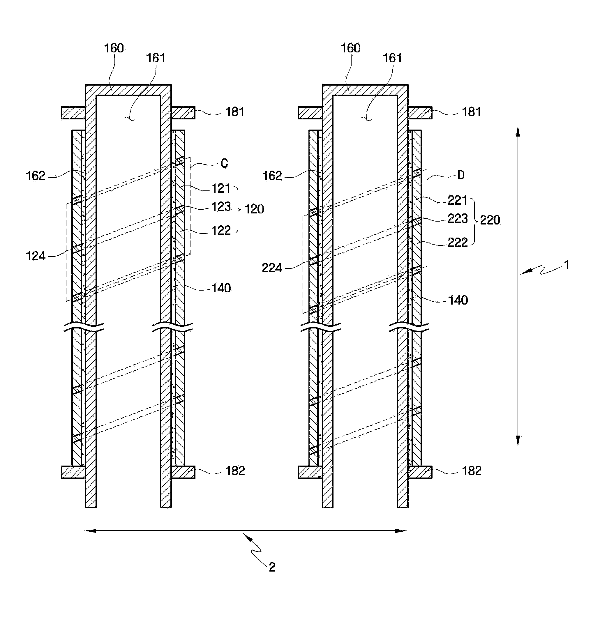
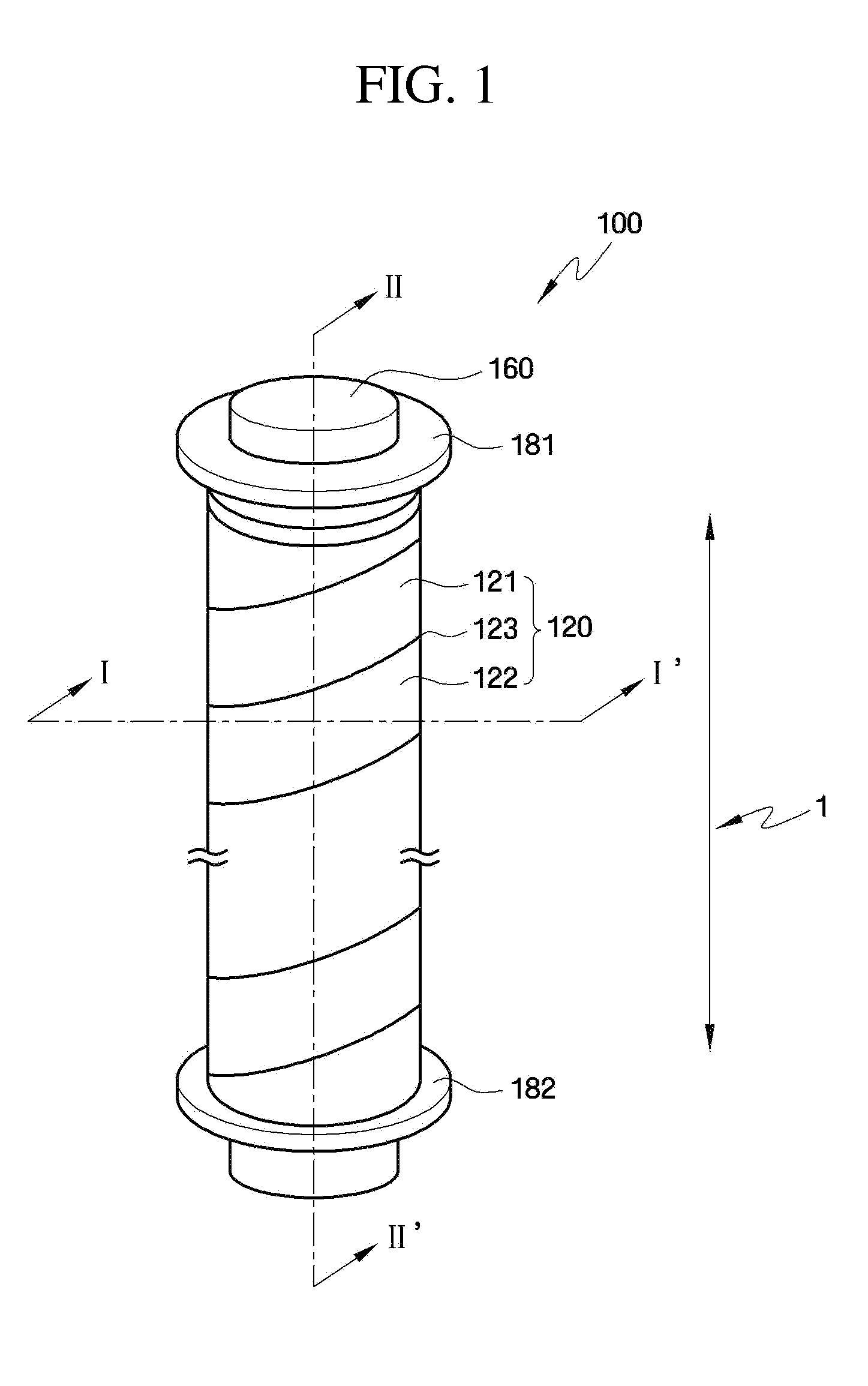
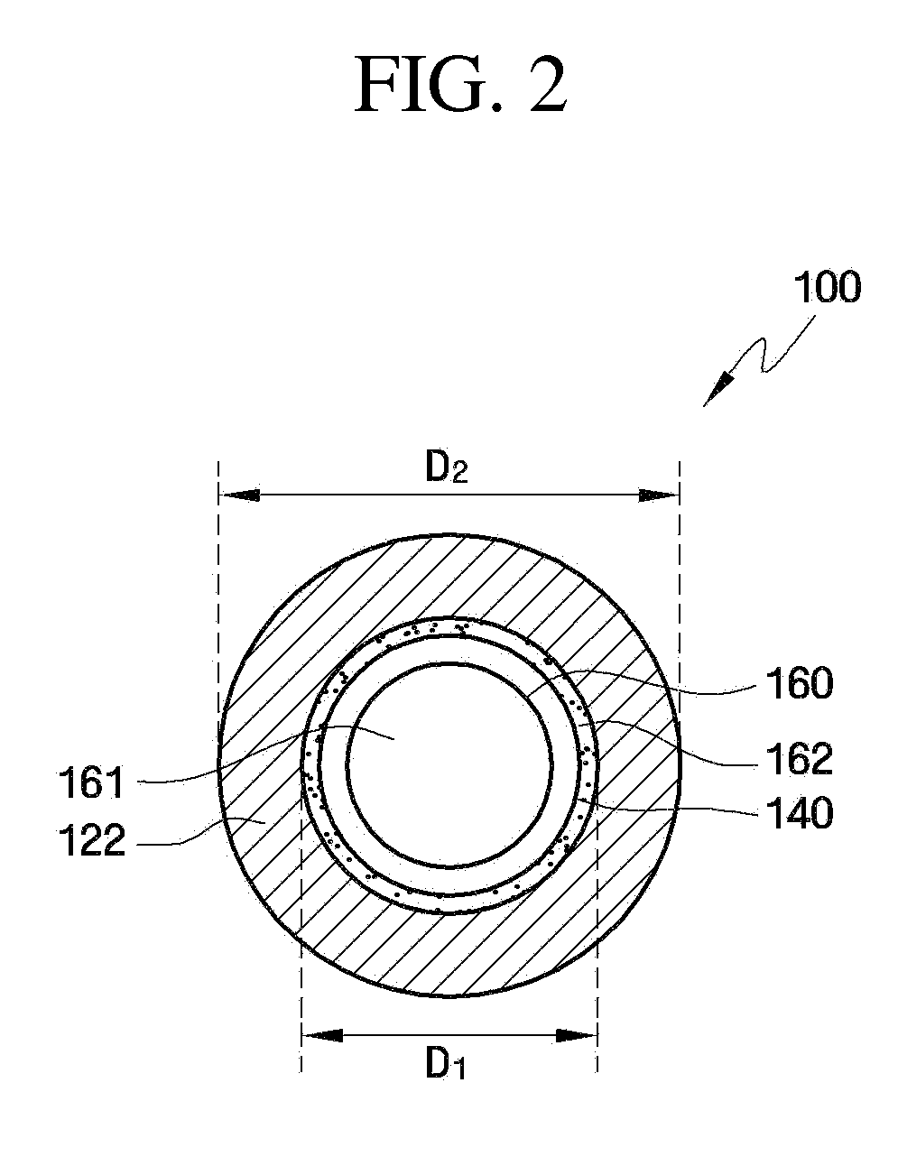
A sputtering target apparatus is provided. The sputtering target apparatus includes a first target assembly including a first target array having a first target, a second target disposed adjacent to the first target, and a first target dividing region disposed between the first and second targets, the first target assembly extending along a first direction, wherein the first target dividing region has a longitudinal cross-section that is oblique with respect to the first direction.

Description

CROSS REFERENCE TO RELATED APPLICATION[0001]This application claims priority from and the benefit of Korean Patent Application No. 10-2009-0072844, filed on Aug. 7, 2009, which is hereby incorporated by reference for all purposes as if fully set forth herein.BACKGROUND OF THE INVENTION[0002]1. Field of the Invention[0003]Exemplary embodiments of the present invention relate to a sputtering target apparatus, and more particularly, to a sputtering target that allows the deposition of a uniform film.[0004]2. Discussion of the Background[0005]Thin films are formed on a substrate such as glass or plastic using metal oxides and ceramic materials as well as metals. In particular, Indium Tin Oxide (ITO) films that are a mixture of Indium oxide (In2O3) and tin oxide (SnO2) have been mostly used as electrodes for flat panel displays including Liquid Crystal Display (LCD), Plasma Display Panel (PDP), and Organic Electroluminescent Display (OEL).[0006]These electrode films are formed by sputter...

Claims


Application Information

Patent Timeline
IPC IPC(8): C23C14/34
CPCC23C14/3407H01J37/3435H01J37/342C23C14/3464C23C14/34
Inventor KIM, DO-HYUNLEE, DONG-HOONJEONG, CHANG-OH
Owner SAMSUNG DISPLAY CO LTD
Learn More