Electrostatic Coalescer

a coalescer and electrostatic technology, applied in electrostatic separation, centrifuges, water/sludge/sewage treatment, etc., can solve the problems of reducing the effectiveness of coalescing, and prior designs of electrostatic coalescers that cannot handle high water cuts. achieve the effect of a larger diameter

Inactive Publication Date: 2011-02-10
AKER PROCESS SYST
View PDF7 Cites 15 Cited by
  • Summary
  • Abstract
  • Description
  • Claims
  • Application Information

AI Technical Summary

Benefits of technology

[0021]It is an advantage that, by imparting a swirling or spiral motion to the fluid, the path taken by the fluid flowing through the narrow passage between the electrodes is longer for a given electrode length. This means that, if the flow regime (defined by the Reynolds Number) is maintained with the required degree of turbulence, the length of the electrodes can be made shorter while still maintaining the required residence time.
[0024]Embodiments of the invention also have the advantage that, in certain circumstances, it is possible to mount the coalescer in a non-vertical orientation. The swirling motion of the flow imparted by the elongates element is sufficient to carry the water droplets such that they do not settle or accumulate to a significant extent next to an electrode. In some circumstances it may be possible to mount the coalescer with the axis of the electrodes oriented horizontally, the swirling motion being sufficient to lift the coalesced water droplets to a sufficient extent that they do not settle, but are carried through to the outlet.
[0026]The invention thus provides an electrostatic coalescer which is of a shorter length compared to known electrostatic coalescers, but with a larger diameter maintaining similar process conditions and capabilities of the, e.g. turbulent flow, electrostatic field strength, residence time. The invention also allows an electrostatic coalescer to be oriented horizontally.

Problems solved by technology

Prior designs of electrostatic coalescers were not able to handle high water cuts due to problems arising from conduction in the water (effectively short-circuiting of the electrodes).
These help to ensure that there are no recirculation paths for the emulsion, which would reduce the effectiveness of the coalescing.
The narrow gaps also help to create a turbulent or transitional flow regime, avoiding laminar flow which would also reduce the effectiveness.
Such a water layer changes, and could adversely affect, the electrostatic field.
However, effective coalescing of droplets in an emulsion requires a certain residence time of the fluid in the electrostatic field.
Space is often at a premium, especially on off-shore production platforms, and in some circumstances the height available may be restricted.

Method used


Image

  • Electrostatic Coalescer
  • Electrostatic Coalescer
  • Electrostatic Coalescer

Examples


Embodiment Construction

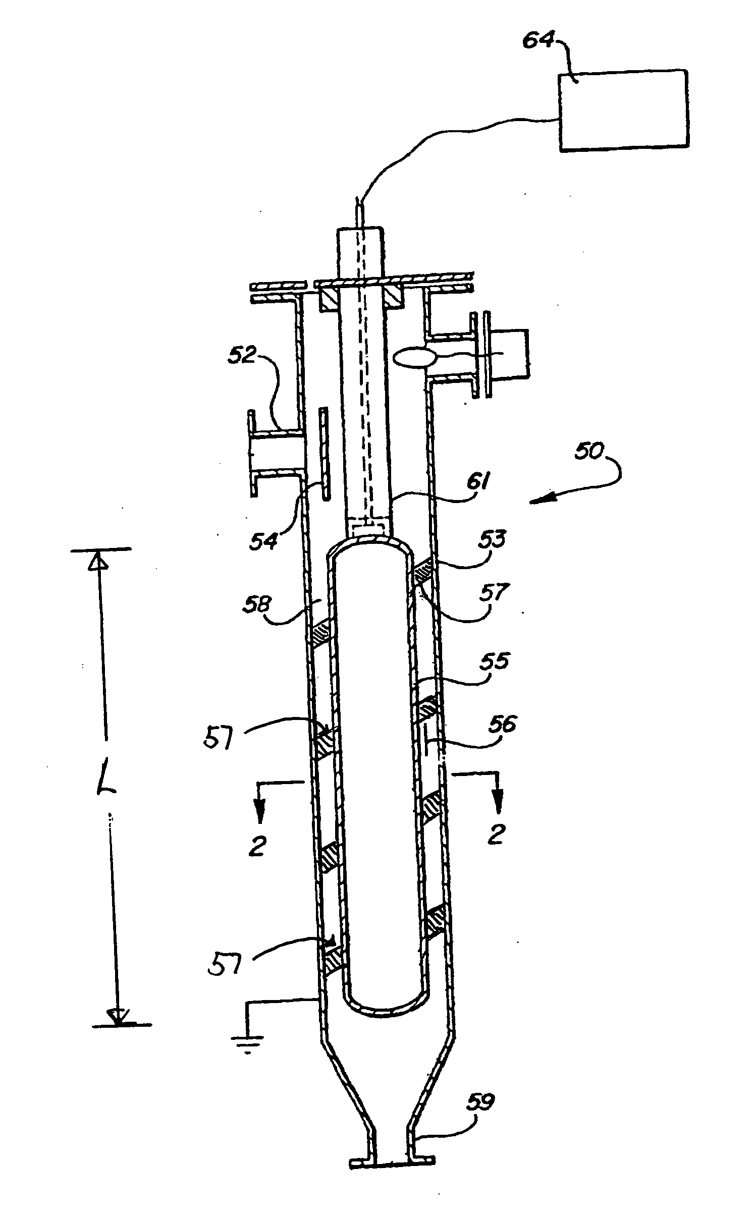
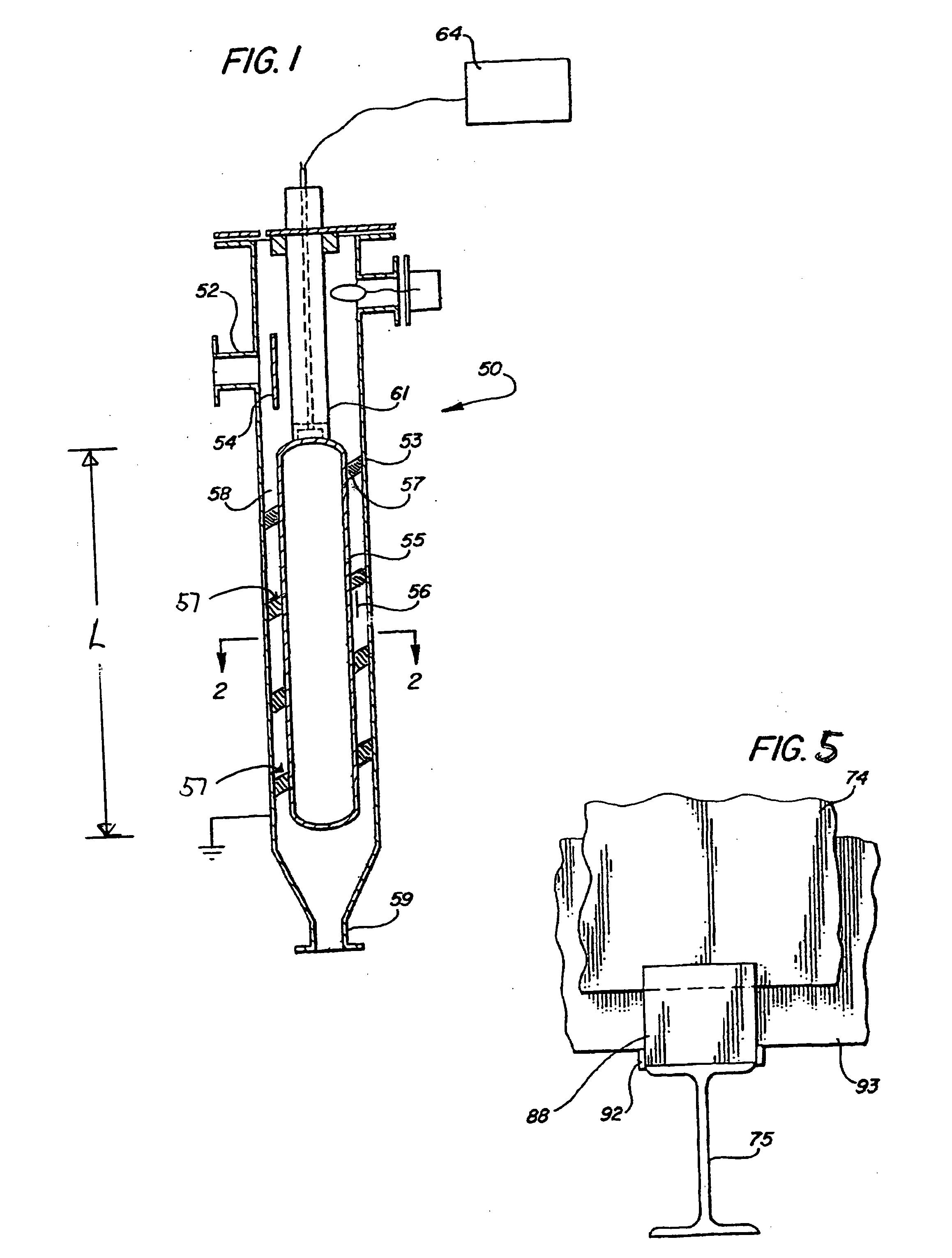
[0036]Referring to FIG. 1, the electrostatic coalescer 50 according to the invention comprises a coalescer 50 having an inlet nozzle 52 for a non-laminar emulsion flow stream into a vertical, exterior pressure-containing shell 53, which is electrically grounded. An internal baffle shield 54 deflects the emulsion flowing into the internal chamber of the pressure-containing shell 53 to the outer edge of the chamber so that the incoming fluid does not impinge on the entrance bushing 61. The coalescer also comprises an internal electrode 55, preferably in the form of an annulus and coated on its external surface with an insulating layer 56, having good dielectric strength, such as a fluropolymer, or the like. A flow gap 58 is thus provided between the insulated electrode 55 and an internal wall of the shell 53. A fluid outlet 59 is provided at the bottom region of the shell 53.

[0037]A helical vane 57 is disposed in the annular flow gap 58 between the electrode 55 and the internal wall s...


PUM


Abstract

An electrically energized compact coalescer (50) comprising an elongated, closed shell (53) having a fluid inlet (52) and a fluid outlet (59); at least one electrode (55) mounted in an internal chamber formed in the closed shell and forming at least one narrow gap (58) between the electrode means and a wall in the closed shell. An external power supply (64) is electrically connected to the electrode and the energized electrode (55) is fully encapsulated with insulation to enable an intense electrostatic field to be applied to an electrically conductive emulsion whereby the flow of emulsion through said at least one narrow gap (58) will be non-laminar. One or more helical vanes (57) are disposed in the narrow gap at an angle with respect to the electrode longitudinal axis and extending for at least a portion of the length (L) of the electrode, whereby the fluid flowing through said narrow gap will follow a spiraling pattern at least partially around the electrode (55).

Description

FIELD OF THE INVENTION[0001]The present invention relates to improvements in electrostatic coalescers, and more particularly, but not exclusively, to compact electrostatic coalescers.BACKGROUND OF THE INVENTION[0002]Coalescers are used extensively in oil and gas production to help separate oil and water mixtures. In many production situations a stream of production fluid contains a mixture in the form of an emulsion. The emulsion is a suspension of very small droplets of one fluid phase (for example water) carried in another fluid phase (for example oil). Coalescers are used to increase the size of the droplets. This helps to break down the emulsion and larger droplets separate much more easily (for example under gravity).[0003]An important development in the use of coalescers was the advent of the Compact Electrostatic Coalescer (CEC®; a registered trademark owned by the applicant / assignee of the present application). This device, which is described in[0004]European Patent No. 1,08...

Claims


Application Information

Patent Timeline
Patent Type & Authority Applications(United States)
IPC IPC(8): B01D17/04
CPCB01D17/0217B03C2201/02B01D17/045B01D17/06
Inventor HANA, MORTEN
Owner AKER PROCESS SYST
Why Eureka
Try Eureka