

Componet, in particular a shell component, which can be joined thermally and/or mechanically, for building a fuselage section of an aircraft
a composite material and fuselage section technology, applied in the field of composite materials, can solve the problems of increasing the weight of the aircraft fuselage section, limited electrical conductivity, carbon fiber reinforced epoxy resin, etc., and achieve the effect of reducing weigh
- Summary
- Abstract
- Description
- Claims
- Application Information
AI Technical Summary
Benefits of technology
Problems solved by technology
Method used
Image

Examples
first embodiment
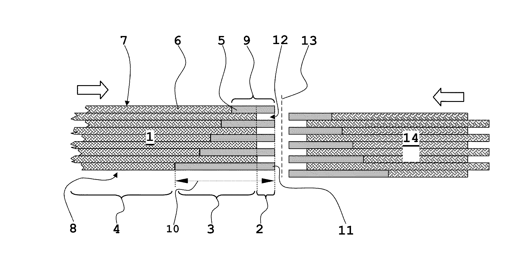
[0032]FIG. 1 illustrates a cross-sectional view of two components variant, implemented according to the invention but not joined yet.
[0033]A first component 1 comprises a border area 2, a hybrid region 3 or mixed region, as well as a surface region 4. In the border area 2 a plurality of electrically conductive metal layers are arranged one on top of the other, wherein one metal layer 5, representative of all the remaining ones, has been given a reference number. In the surface region 4 the component 1 exclusively comprises a plurality of composite-material layers arranged over the entire area one on top of the other, wherein one of the composite-material layers 6, representative of all the remaining ones, has been given a reference number. In contrast to this, in the hybrid region 3 each metal layer 5 alternates with a composite-material layer 6, wherein at the top 7 and at the bottom 8 of the component 1 in each case a metal layer finishes the layer structure. The metal layers 5 i...
second embodiment
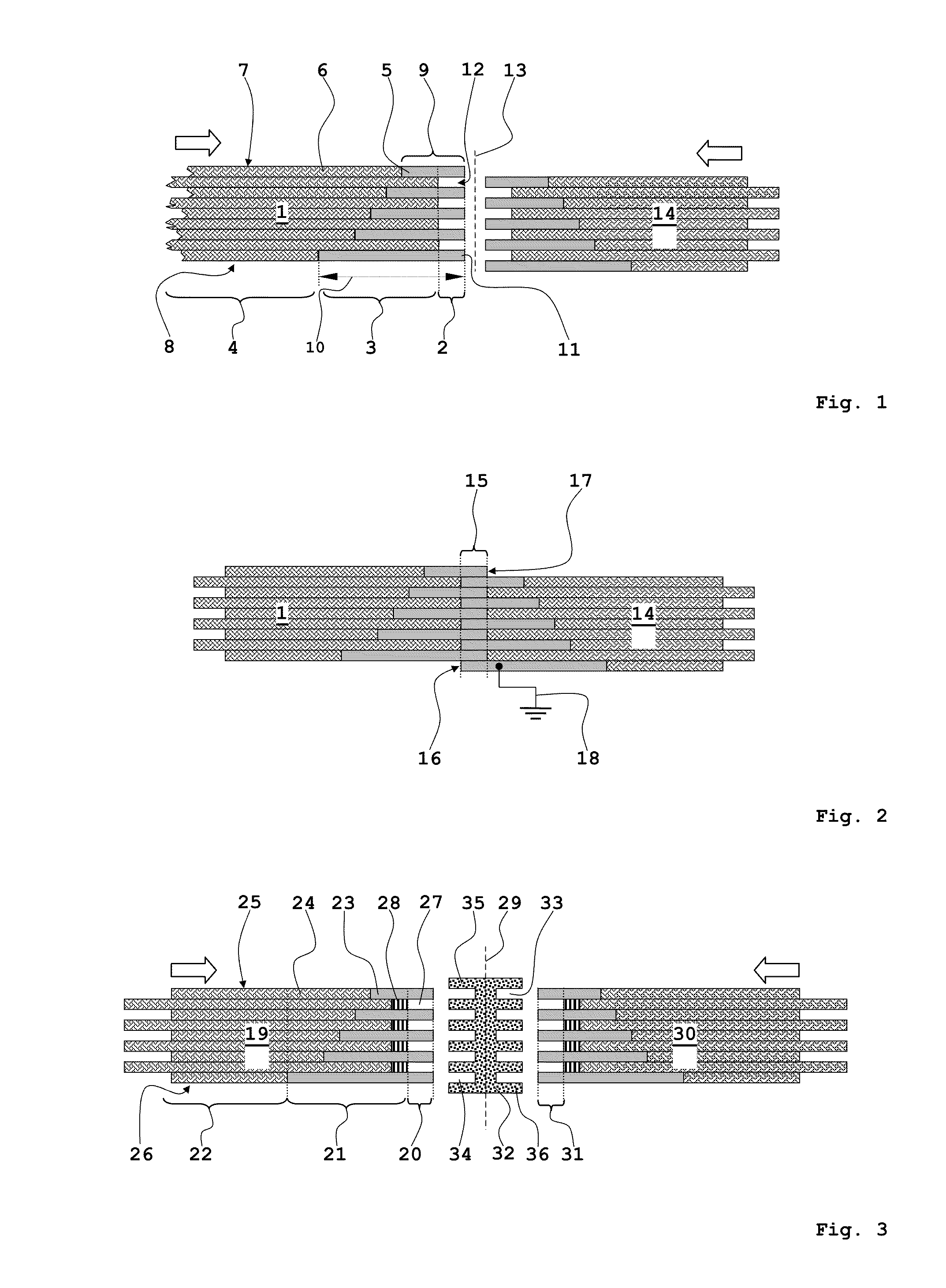
[0039]FIG. 3 shows a cross-sectional view of two not yet joined components variant.
[0040]A first component 19 comprises a narrow metal border area 20 which makes a transition to a hybrid region 21 and subsequently to a surface region 22. The border area 20 in turn comprises a plurality of metal layers, arranged one on top of the other so as to be spaced apart, wherein one of said metal layers is designated 23. The hybrid region 21 is constructed in an alternating layer sequence comprising metal layers 23 and composite-material layers 24. Preferably, the top 25 and the bottom 26 of the component 19 comprise a metal layer each. In the region of the top 25 of the left-hand component 19 the metal layer 23 and the composite-material layer 24 abut each other. The same applies to the composite-material layers and metal layers (not designated by reference characters) situated in the region of the bottom 26 of the component 9, as well as to all the further layers.
[0041]A cavity, comprising ...
third embodiment
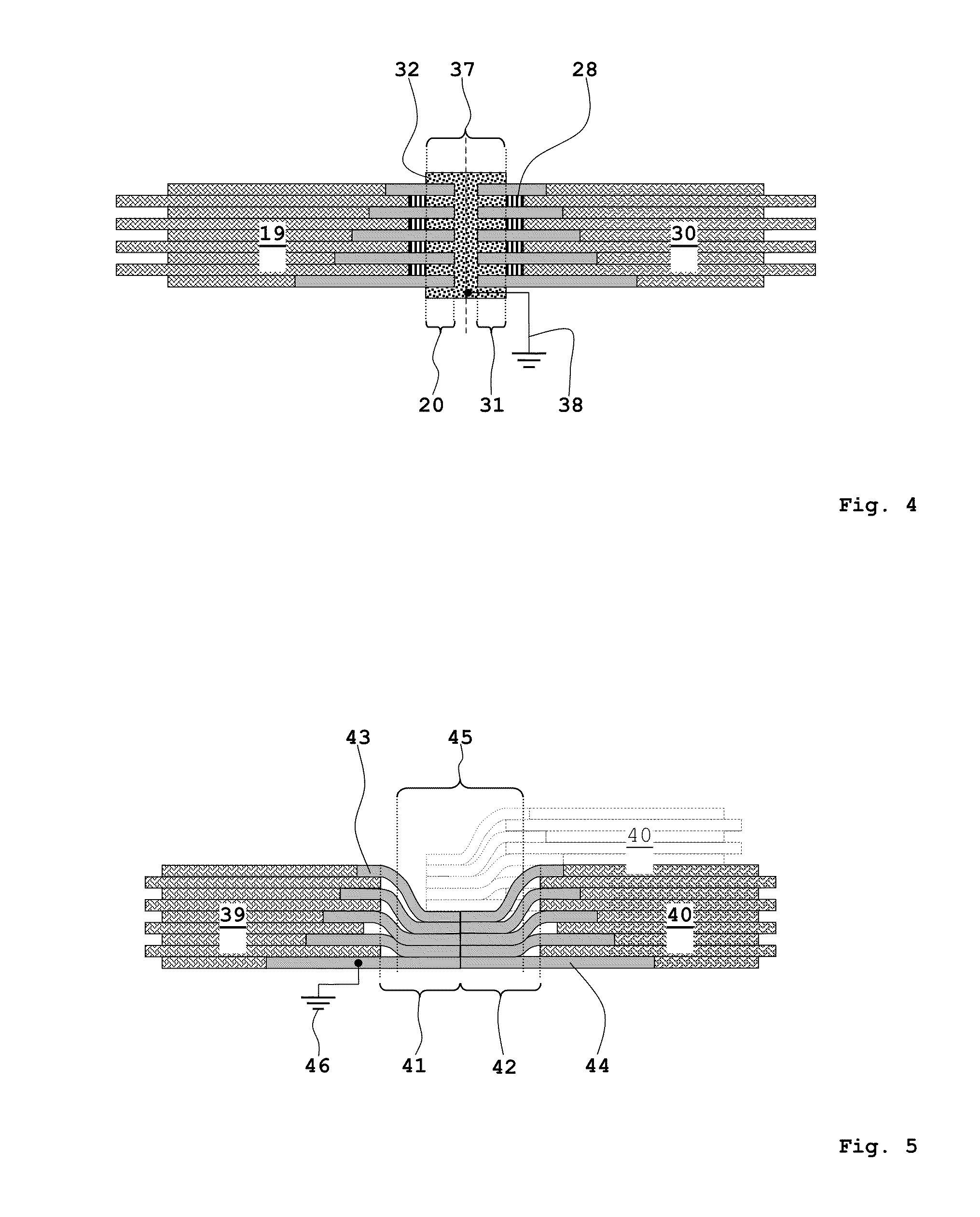
[0050]FIG. 5 shows the components. In contrast to the first two variants of the components according to FIGS. 1 to 4, the components 39, 40 comprise metal layers 43, 44 in the border areas 41, 42, which metal layers are arranged directly one on top of the other. There are no regular or rectangular cavities between the metal layers. This design of the metal layers, which is curved when compared to the embodiment according to FIGS. 1 to 4, can, for example, be achieved by means of a forming process. If applicable, this forming process requires the lengths of the metal layers in the border areas 41, 42 to be varied in such a way that a flush finish of the metal layers, in other words a straight vertical edge, results.
[0051]In the region of a joint 45, which is to be produced by means of a suitable thermal joining process, the metal layers 43, 44 of the components 39, 40 in each case form a “compact” metal layer. In order to create the electrically conductive joint 45 the border areas 4...
PUM
| Property | Measurement | Unit |
|---|---|---|
| Thickness | aaaaa | aaaaa |
| Electrical conductivity | aaaaa | aaaaa |
| Plasticity | aaaaa | aaaaa |
Abstract
Description
Claims
Application Information