Sheet mass measuring unit

a mass measurement and paper sheet technology, applied in the direction of instruments, electrographic processes, transportation and packaging, etc., can solve the problems of inability to accurately measure the mass of paper sheets, inability to reduce throughput, drive shafts, etc., and achieve the effect of high accuracy and enhanced throughpu

a mass measurement and paper sheet technology, applied in the direction of instruments, electrographic processes, transportation and packaging, etc., can solve the problems of inability to accurately measure the mass of paper sheets, inability to reduce throughput, drive shafts, etc., and achieve the effect of high accuracy and enhanced throughpu

US20110031683A1Inactive Publication Date: 2011-02-10KK TOSHIBA

Image

  • Sheet mass measuring unit
  • Sheet mass measuring unit
  • Sheet mass measuring unit

Examples


Embodiment Construction

[0024]An embodiment of the invention will be described in detail with reference to the accompanying drawings.

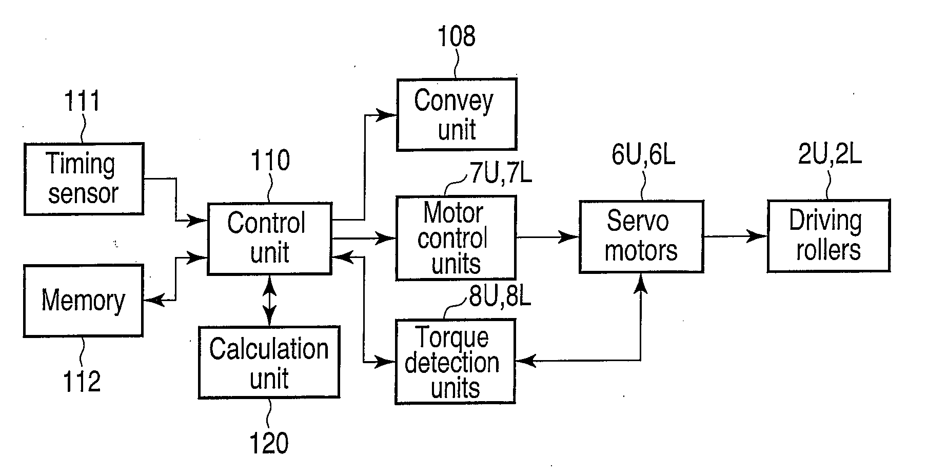
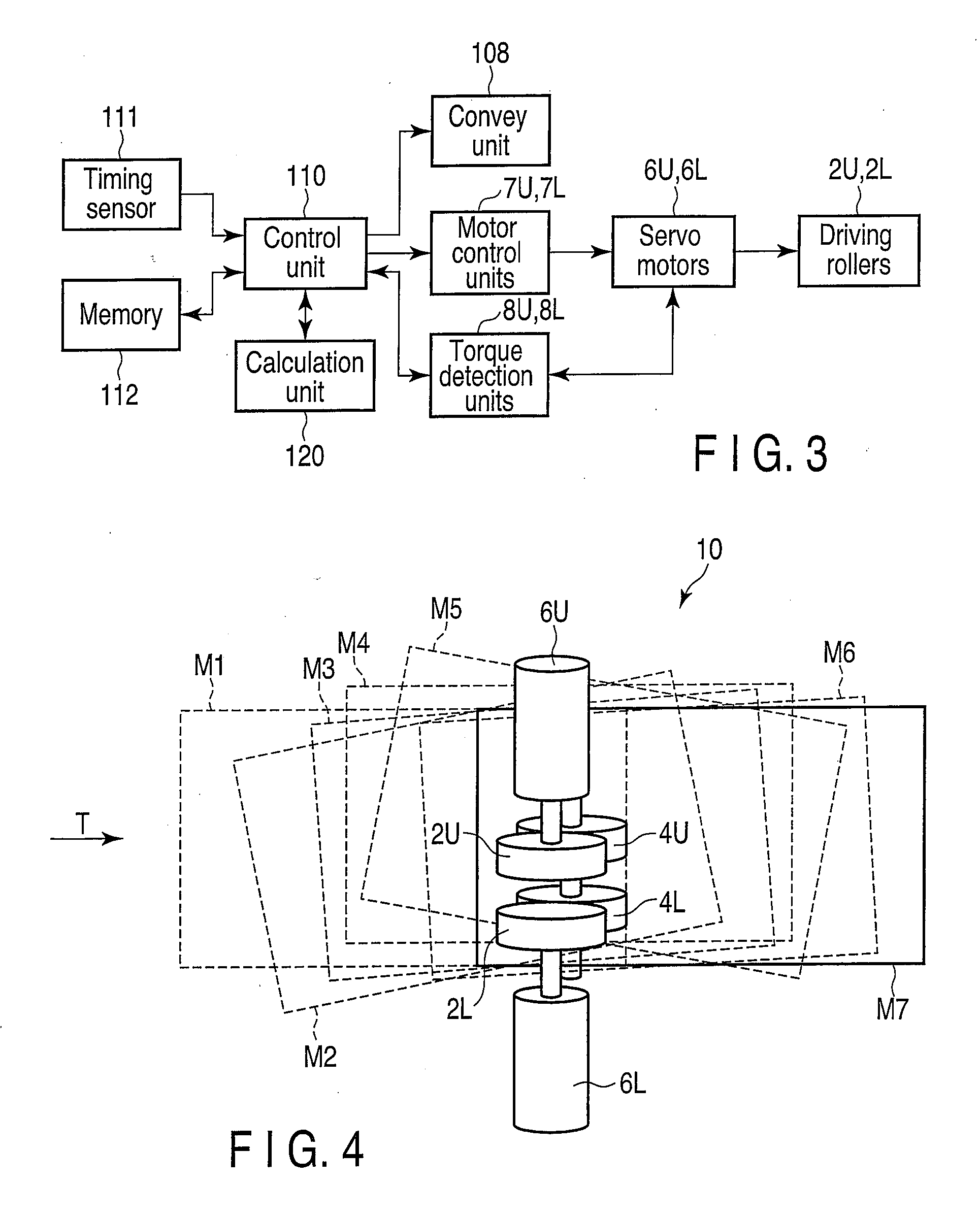
[0025]FIG. 1 is a schematic block diagram illustrating a mail matter selection / pickup / stamping apparatus 100 (hereinafter referred to simply as “the apparatus 100”) that incorporates a mass measuring unit according to the embodiment of the invention.

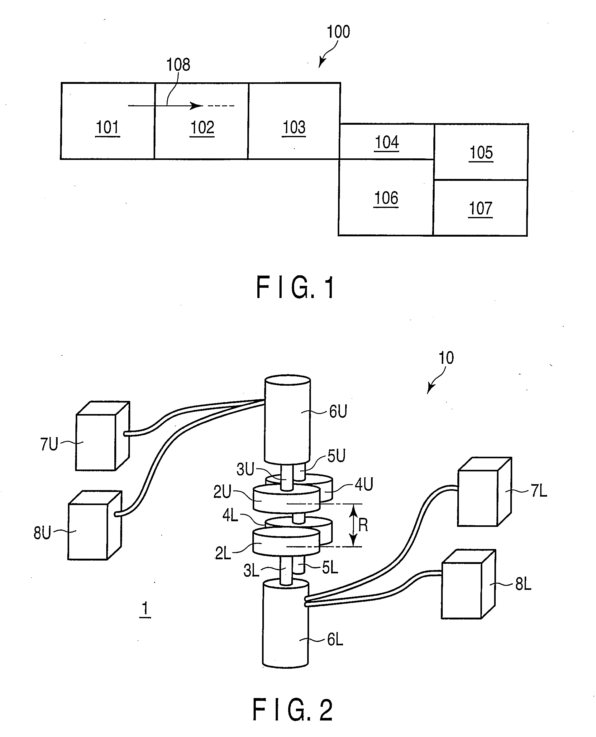
[0026]The apparatus 100 comprises a supply unit 101, a mechanical detection unit 102, an OCR scanner unit 103, a twisting / reversing unit 104, a switchback unit 105, a stamp unit 106 and a delivery / stacker unit 107. The apparatus 100 also comprises a convey unit 108 for conveying mail matters M through the above-mentioned units. The apparatus 100 also comprises an operation panel (not shown) for instructing the apparatus to perform various operations, to switch the operation mode and to display abnormality.

[0027]The supply unit 101 simultaneously receives a plurality of mail matters M of standard sizes, mass and widths (perpendicul...


PUM


Abstract

A mass measuring unit includes two driving rollers vertically separate from each other and intersecting the direction of conveyance of a mail matter. Servo motors for driving the driving rollers are connected to torque detection units. A control unit controls motor control units to cause them to impart a rate difference between the driving rollers to rotate the mail matter during its conveyance, and to cause the torque detection units to detect the torque values of the servo motors. The control unit compares the thus detected torque values with the torque values of the servo motors detected when the servo motors are idling without rotating the mail matter, thereby measuring the mass of the mail matter using a calculation unit.

Description

CROSS-REFERENCE TO RELATED APPLICATIONS[0001]This application is based upon and claims the benefit of priority from prior Japanese Patent Application No. 2009-185952, filed Aug. 10, 2009, the entire contents of which are incorporated herein by reference.BACKGROUND OF THE INVENTION[0002]1. Field of the Invention[0003]The present invention relates to an apparatus for measuring the mass of a paper sheet, such as a mail matter, and more particularly, to an apparatus for measuring the mass of a paper sheet conveyed at a relatively high rate, without stopping the conveyance of the sheet.[0004]2. Description of the Related Art[0005]Jpn. Pat. Appln. KOKAI Publication No. 2005-162407 (hereinafter, patent document 1), for example, discloses a mass detection apparatus as an apparatus for measuring the mass of a paper sheet during conveyance of the same. In the apparatus disclosed in patent document 1, the rotational rate of a driving roller provided along a conveyor path is varied to gradually...

Claims


Application Information

Patent Timeline
10 Feb 2011
Publication
US20110031683A1
IPC
B65H5/06
CPC
B07C5/165; B07C5/20; G03G2215/00742; G01G19/005; G01G19/4148; G01G17/02
Inventors
ASARI, YUKIO; MITSUYA, YUSUKE