Energy harvesting buoy

a technology of energy harvesting and buoys, which is applied in the direction of electric generator control, machines/engines, transportation and packaging, etc., can solve the problems of limited efficiency and performance level of existing energy extraction systems, limitations of prior art energy-extracting technologies, and difficulty in deployment of buoys in open sea depth

Inactive Publication Date: 2011-02-10
PFG IP +1
View PDF9 Cites 19 Cited by
  • Summary
  • Abstract
  • Description
  • Claims
  • Application Information

AI Technical Summary

Benefits of technology

[0010]The wave-powered air pressurization means in the energy-harvesting buoy of the invention takes advantage of waves or ocean swell energy in a different manner than the prior art methods described above. The preferred embodiment of the energy-harvesting buoy herein generates pressurized air that is, in turn, stored in an onboard air tank or pressure accumulator. The device functionally acts as a piston and check valve in an air-pump much like the one used for bicycles.

Problems solved by technology

These prior art energy-extracting technologies have limitations due to the need for anchoring, specific location and limited performance and efficiency in the case of vibration harvesters.
The requirement for operation in open sea where marine energy may be insufficient to drive prior art devices sets a limit to the efficiency and performance level of existing energy-extraction systems.
Additionally, the depth in open sea complicates the deployment of a buoy if rigid anchoring to the sea floor is required.

Method used


Image

  • Energy harvesting buoy
  • Energy harvesting buoy

Examples


Embodiment Construction

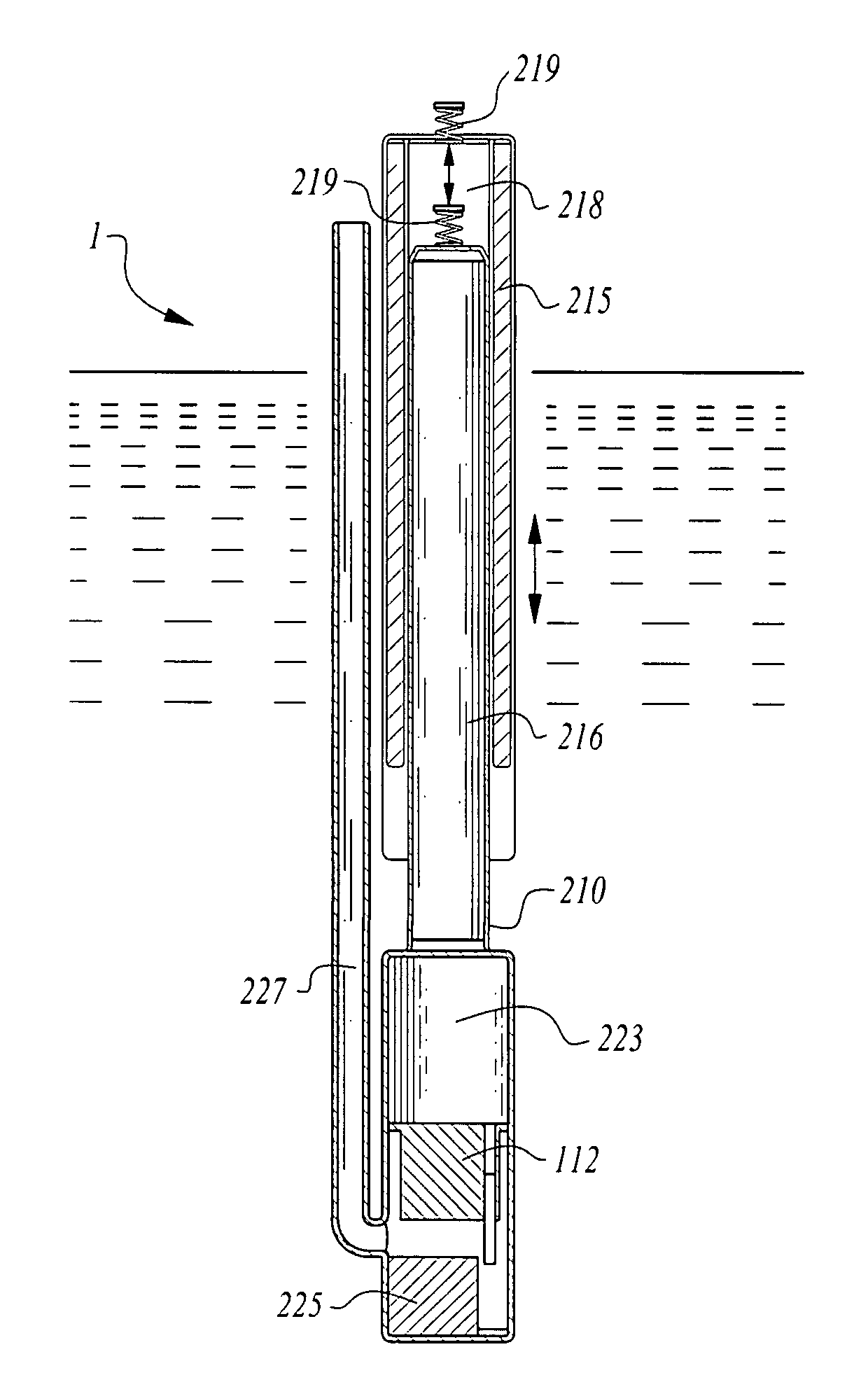
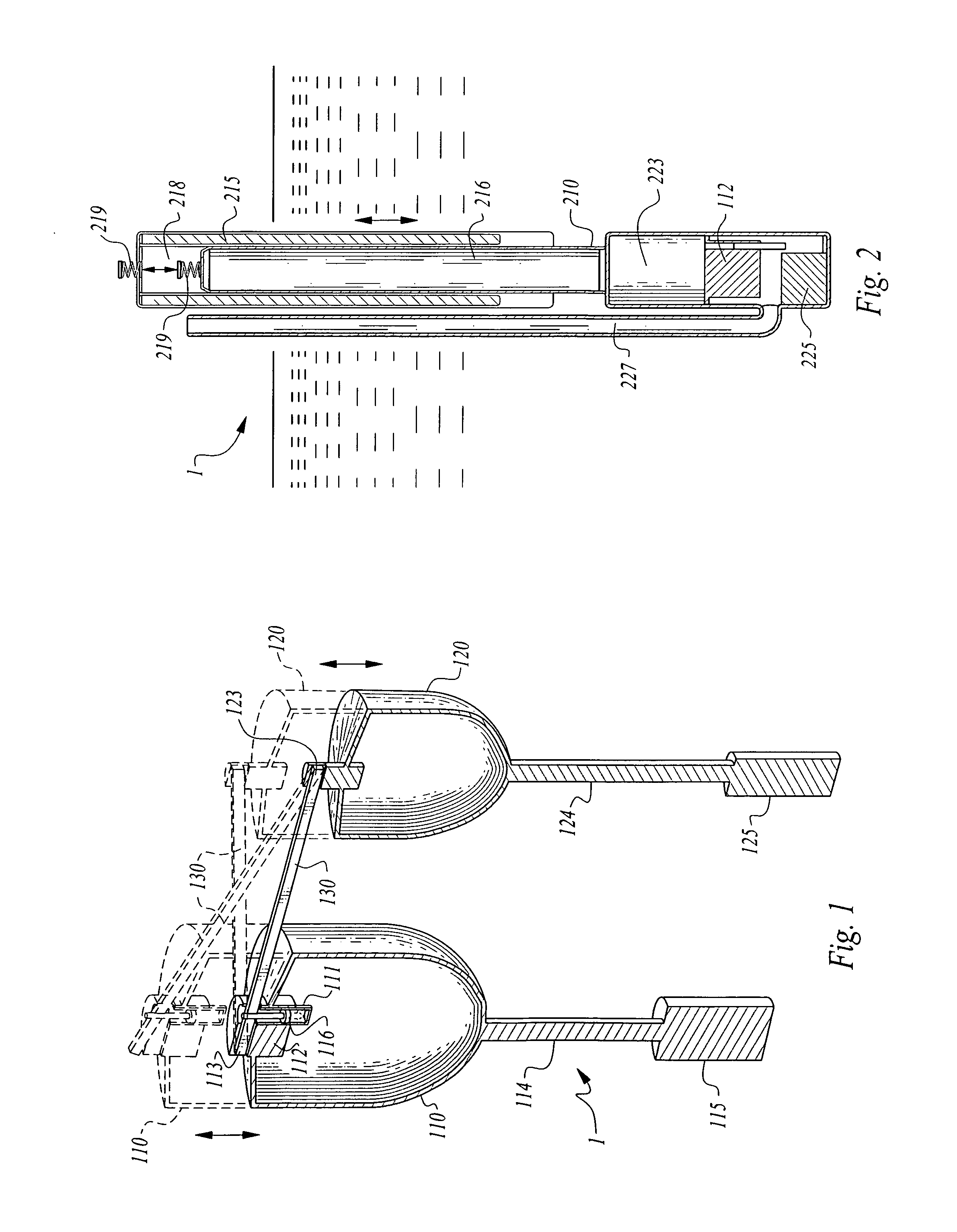
[0034]Turning now to the figures wherein like numerals define like elements among the several views, FIG. 1 shows a preferred embodiment of the energy harvesting buoy assembly 1.

[0035]The preferred embodiment of energy-harvesting buoy 1 is comprised of a first float 110 and a second float 120. First float 110 is further comprised of a modulated or unmodulated air-pressure generator 112 disposed on or proximal first float 110. This air-pressure generator 112 is preferably a piezo-electric generator as described above.

[0036]First float 110 is further comprised of a first stabilizing rod 114, such as a prolate or elongate stabilizing rod in cooperation with a first weight 115 which is used to stabilize first float 110 and generally maintain the float member a vertical orientation of each float member while in operation in water much as the weighted keel of a sailboat is used.

[0037]A similar structure is used in second float 120 where second stabilizing rod 124 and second weight 125 are...


PUM


Abstract

An energy-harvesting buoy is provided comprising an air-pressure generator, such as a piezo-electric generator, or any other generator that can harvest energy from an air pressure. The energy harvesting buoy consists of a first float and a second float. An air pressure is created when relative vertical motion occurs between the first float and the second float which drives an air pressurization means such as a piston driven air pump using a linkage member pivotably mounted between the respective floats. The generator uses the air pressure from the air pressurization means to drive the generator to generate electrical power.

Description

CROSS-REFERENCE TO RELATED APPLICATIONS[0001]This application claims the benefit of U.S. Provisional Patent Application 61 / 273,575, filed on Aug. 6, 2009, entitled “Energy Harvesting Buoy” pursuant to 35 USC 119, which provisional application is incorporated fully herein by reference.STATEMENT REGARDING FEDERALLY SPONSORED RESEARCH AND DEVELOPMENT[0002]Not applicable.DESCRIPTION[0003]1. Field of the Invention[0004]The invention relates generally to the field of energy-generation technology. More specifically, the invention relates to a buoy assembly that generates electrical energy using a modulated or unmodulated air-pressure generator.[0005]2. Background of the Invention[0006]Several ocean energy extraction concepts are known and presently used to some degree in various marine applications. These include, but are not limited to, anchored energy-generating devices where the relative motion between a rigidly anchored component and a wave-driven flap is used to drive a generator, the...

Claims


Application Information

Patent Timeline
Patent Type & Authority Applications(United States)
IPC IPC(8): F03B13/16H02J7/32
CPCY02E10/38F03B13/20Y02E10/30
Inventor SAPIR, ITZHAKBOYD, W. ERIC
Owner PFG IP
Why Eureka
Try Eureka