Cryogenic insulation attachment

a technology of fiber reinforced forms and attachments, which is applied in the field of attachments of cryogenic insulation, can solve the problems of difficult manipulation of aerogels, one of the best known insulators, and the fabricated carbon steel materials that are not suitable for cryogenic temperatures, and achieve the effect of preventing heat leakage and preventing heat leakag

Inactive Publication Date: 2011-02-10
CONOCOPHILLIPS CO
View PDF10 Cites 18 Cited by
  • Summary
  • Abstract
  • Description
  • Claims
  • Application Information

AI Technical Summary

Benefits of technology

[0010]The present invention provides a method of affixing an attachment means for insulating an apparatus capable of operating at cryogenic temperatures or an apparatus able to contain equipment capable of operating at cryogenic temperatures, the method comprises: placing an insulation means in the interior surface of the apparatus at a desired location, wherein the insulation means is removable, wherein the insulation means includes a thermal insulation panel, wherein the thermal insulation panel is made of a material capable of preventing heat leakage, wherein the thermal insulation panel includes an interior surface which is the surface directly connected to the apparatus and a exterior surface, wherein the thermal insulation panel is aerogel and a plug cut from the thermal insulation panel, wherein the plug is the exact size of an attachment means; and placing the attachment means in the plug cut from the thermal insulation panel thereby affi

Problems solved by technology

The container is fabricated from carbon steel material not suitable for exposure to cryogenic temperatures.
Manipulation of aerogels, one of the best known insulators, can be very challenging given the fragility of this material form.
However, few methodologies have yet been developed for securing or attaching these

Method used


Image

  • Cryogenic insulation attachment
  • Cryogenic insulation attachment
  • Cryogenic insulation attachment

Examples


Embodiment Construction

[0016]Reference will now be made in detail to embodiments of the invention, one or more examples of which are illustrated in the accompanying drawings. Each example is provided by way of explanation of the invention, not as a limitation of the invention. It will be apparent to those skilled in the art that various modifications and variation can be made in the present invention without departing from the scope or spirit of the invention. For instances, features illustrated or described as part of one embodiment can be used on another embodiment to yield a still further embodiment. Thus, it is intended that the present invention cover such modifications and variations that come within the scope of the appended claims and their equivalents.

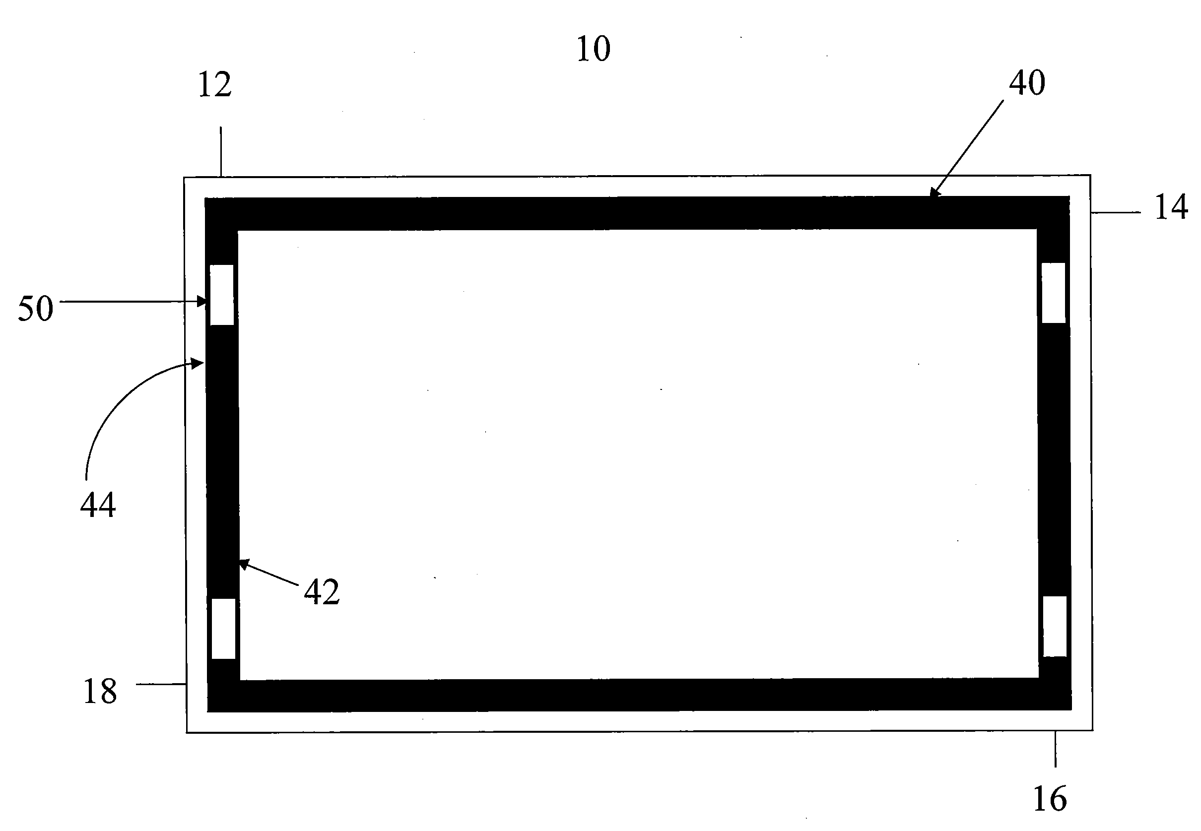
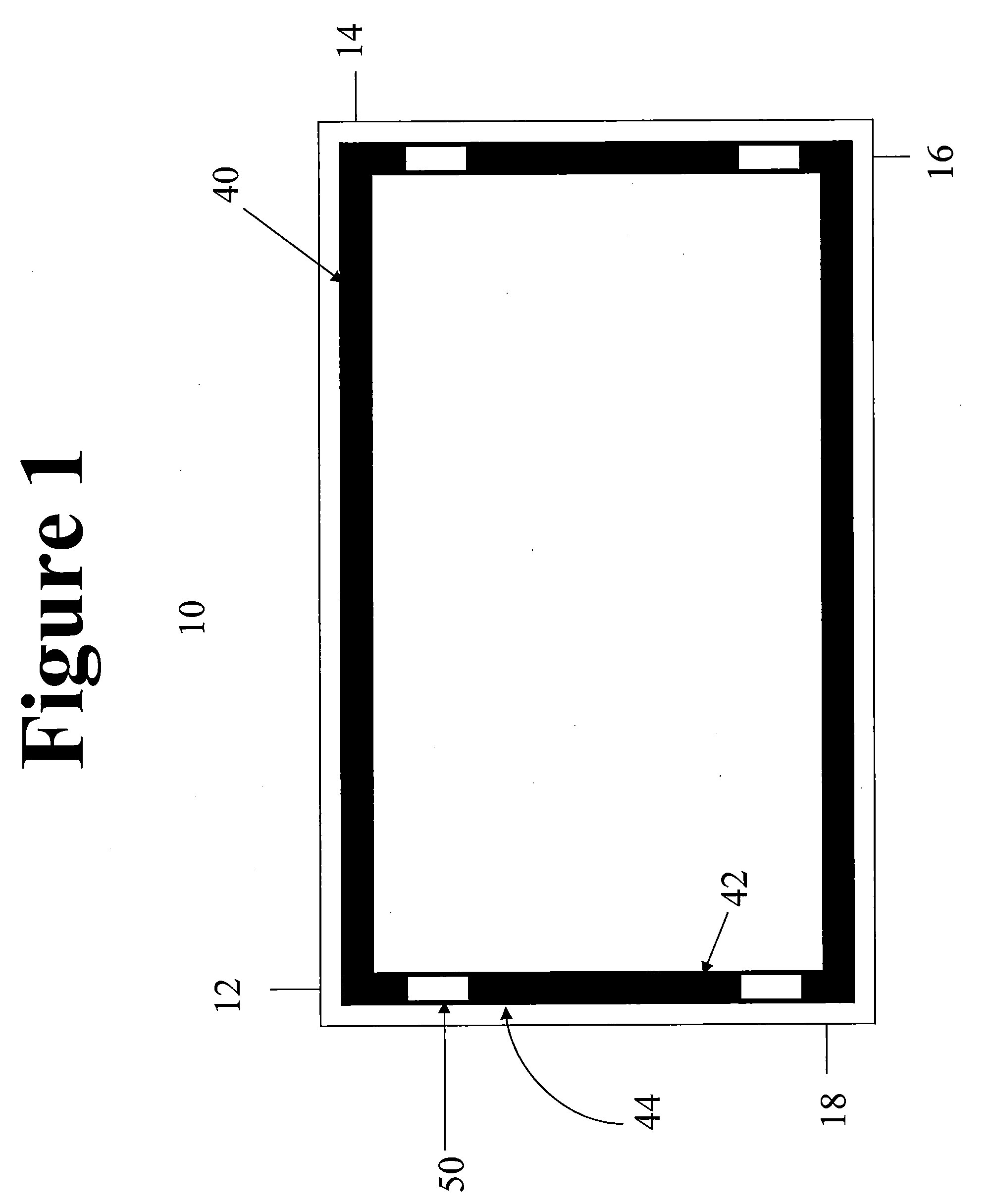
[0017]With reference to FIG. 1, a container 10 is illustrated that is of rectangular transverse cross-section with four connected walls 12, 14, 16 and 18. Container 10 can serve the function as a thermal insulator capable of containing equipment ope...


PUM

PropertyMeasurementUnit
Temperatureaaaaaaaaaa
Sizeaaaaaaaaaa
Thermal propertiesaaaaaaaaaa

Abstract

An attachment means of insulation within a container to prevent heat leakage from the ambient to an apparatus located within the container that operates at a cryogenic temperature.

Description

CROSS-REFERENCE TO RELATED APPLICATIONS[0001]This application claims priority benefit under 35 U.S.C. Section 119(e) to U.S. Provisional Patent Ser. No. 61 / 232,214 filed on Aug. 7, 2009 the entire disclosure of which is incorporated herein by reference.FIELD OF THE INVENTION[0002]The present invention relates to an attachment of insulation to insulate an apparatus operating at cryogenic temperature within a container from heat leakage through the container walls.BACKGROUND OF THE INVENTION[0003]In many industrial applications, an apparatus that is designed to operate at cryogenic temperatures is located within an insulated container to minimize heat leakage from the ambient to the apparatus.[0004]An example of an apparatus that has operational temperature requirements is a cryogenic distillation apparatus in which air is compressed, purified and then cooled to a temperature at or near its dew point for distillation in one or more distillation columns to separate lighter components s...

Claims


Application Information

Patent Timeline
IPC IPC(8): F25D23/06B23P15/26
CPCE04B1/76F17C1/12F17C2203/017F17C2203/0325F17C2203/0341F17C2221/033Y10T29/49359F17C2223/033F17C2260/033F25J3/04945F25J1/0261F25J3/0295F25J2290/30F17C2223/0161
Inventor GENTRY, MATTHEW C.WILSON, STUART L.
Owner CONOCOPHILLIPS CO
Why Eureka
Try Eureka