Dimmable LED device with low ripple current and driving circuit thereof

a technology of led lighting and low ripple current, which is applied in the direction of electric variable regulation, process and machine control, instruments, etc., can solve the problems of not being suitable for operating led lighting devices, not easy for users to regulate the intensity of led lighting devices, and using ac light dimmer, etc., to reduce output ripple current, and increase output capacity.

Inactive Publication Date: 2011-02-10
PHIHONG TECH CO LTD
View PDF3 Cites 44 Cited by
  • Summary
  • Abstract
  • Description
  • Claims
  • Application Information

AI Technical Summary

Benefits of technology

[0007]In accordance with a preferred embodiment of the present invention, there is provided a dimmable LED device with a driver circuit for reducing the output ripple current.
[0010]In an exemplary embodiment, inside the LED device has a secondary forward winding and a phase cut-off detection circuit added for providing an output current reference level which can enable the reduction of output ripple current.
[0011]In an exemplary embodiment, the LED lighting device enable the flyback converter with dimmable light intensity ability to increase the output capacity greatly and reduce output ripple current which can stabilize the LED's output light intensity. Therefore, the lifetime of LED can be extended and the degraded of flicker index can also be avoided.
[0012]In addition, in an exemplary embodiment, there is no need for applying micro controller unit (MCU) to control the gain of the dimmable light. Therefore, the range of the dimmable light level will be increased, the power consumption also be reduced, and can be matched to the existing dimmer or lighting infrastructure.

Problems solved by technology

However, the ways of driving conventional light lamps are different from the LED lighting devices.
It is not easy for users to regulate the intensity of the LED lighting devices, so the conventional way of using AC light dimmer is not suitable for operating the LED lighting devices.
Typical prior art, phase-modulating LED driver with flyback converter can only allow the usage of input / output capacitors with small capacity for phase-modulating light dimming.
The main drawback of the usage of input / output capacitors with small capacity is that the output ripple current will cause the LEDs overheated and shorten their lifetime, even further result an unstable output and led to light flicking.

Method used


Image

  • Dimmable LED device with low ripple current and driving circuit thereof
  • Dimmable LED device with low ripple current and driving circuit thereof
  • Dimmable LED device with low ripple current and driving circuit thereof

Examples


Embodiment Construction

[0033]Reference will now be made in detail to embodiments of the present invention, examples of which are illustrated in the accompanying drawings.

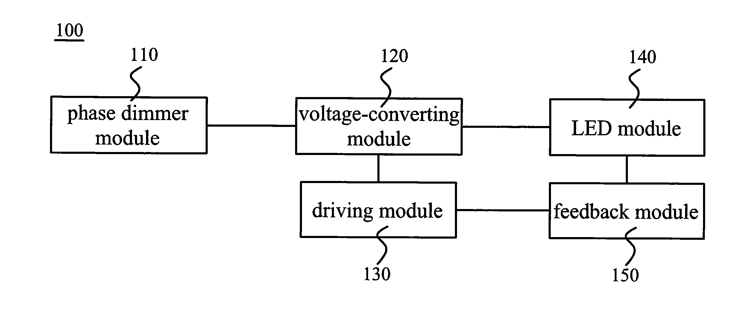
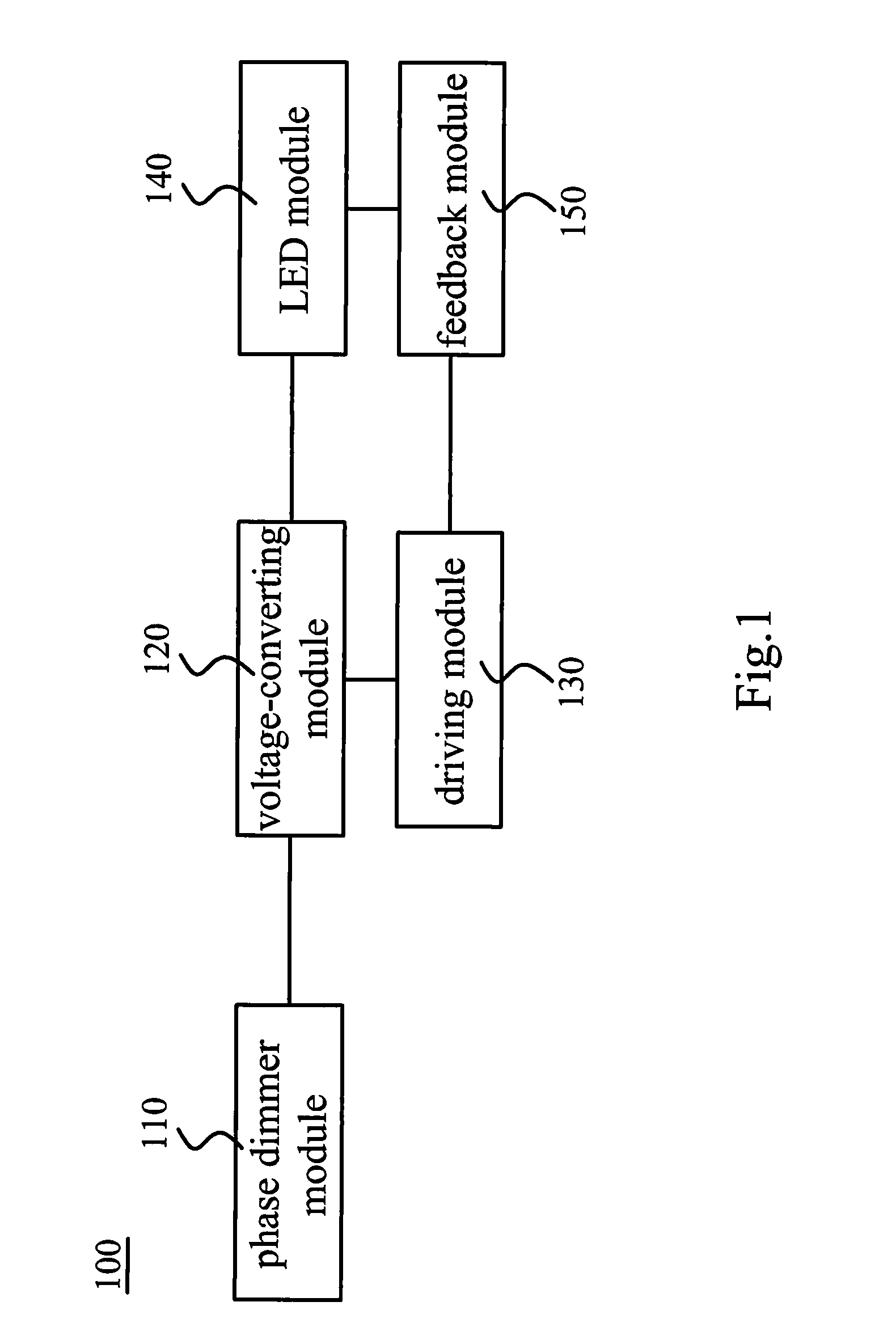
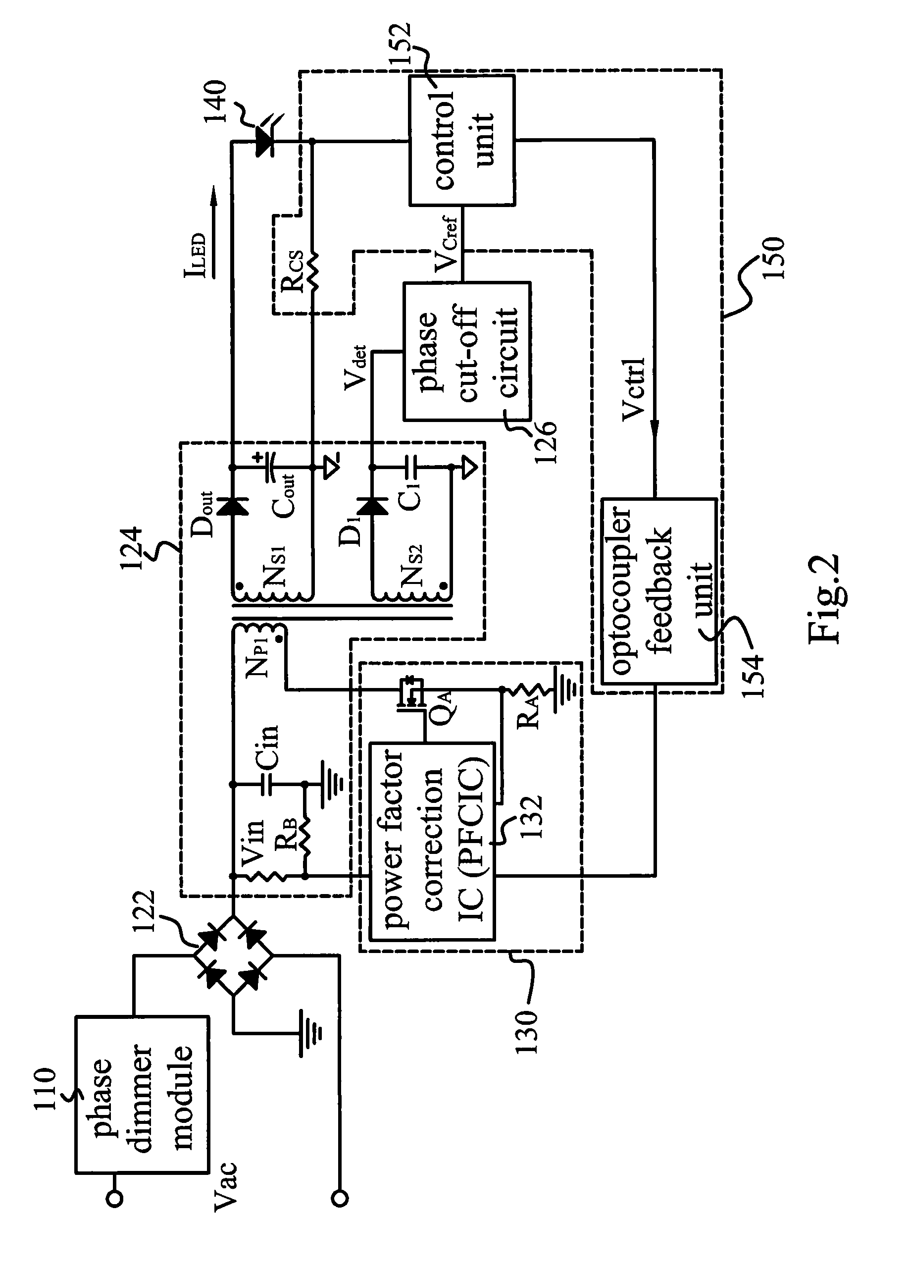
[0034]In the present invention, a LED driver based on a single stage power factor correction flyback (PFC-Flyback) converter circuit is fabricated. Utilizing line voltage amplitude and waveform to regulate the input current will reduce the phase and waveform distortion between the input current and the in-line voltage and increase the power factor. This will greatly reduce the virtual work dispassion and energy consumptions, therefore obtain the purpose of energy-saving.

[0035]As mentioned above, in the present invention, the LED driving circuit is based on the single stage PFC-Flyback converter circuit which is suit for regulating the light intensity on the phase-modulating dimmer of the line voltage. Either the leading or trailing edge of the input voltage signal has been cut-off by the phase dimmer module, the output current of the LED ...


PUM


Abstract

A dimmable light emitting diode (LED) device with low ripple current includes a LED module, a phase dimmer, a voltage converting module, a driving module and a feedback module. The flyback converter of the voltage converting module adds a secondary forward winding connecting to a phase cut-off detector to provide a detecting voltage in proportion to current level of the output current across the LED module.

Description

FIELD OF THE INVENTION [0001]The present invention relates generally to a light emitting diode (LED) device and, more particularly, to a low ripple current dimmable LED device and its driving circuit.BACKGROUND OF THE INVENTION [0002]The light intensity of conventional lamps is mainly controlled by their input current. Therefore, a dimmable lamps based on the conventional technique which was utilizing an AC light dimmer to modulate the phase of input AC voltage then output a phase-modulating AC voltage. Users can use a control device on the AC light dimmer to control the alternating light dimmer, modulate the phase of AC voltage, and enable the phase-modulating AC voltage for dimming brightness or intensity.[0003]The brightness of the lamp is determined by the output phase-modulating AC voltage from the AC light dimmer. If the voltage level becomes lower after modulating the phase of the AC voltage, the light intensity of the lamp will become dimmer; on the contrary, if the voltage ...

Claims


Application Information

Patent Timeline
Patent Type & Authority Applications(United States)
IPC IPC(8): H05B37/02H05B44/00
CPCH05B33/0815H05B45/382H05B45/38H05B45/355H05B45/385
Inventor CHU, CHUNG-JENCHEN, YI-JINGCHUNG, HUNG-CHUN
Owner PHIHONG TECH CO LTD
Why Eureka
Try Eureka