Quantum entanglement generating system and method, and quantum entanglement generating and detecting system and method

a generation system and quantum entanglement technology, applied in the direction of light demodulation, instruments, measurement devices, etc., can solve the problems of difficult to maintain the relative optical path length between these two paths, difficult to bring the light resonators into simultaneous resonance with these two light beams, and the quality of quantum entanglement to deteriorate, so as to achieve the effect of generating a quantum entanglement stably and improving the stability of homodyne detection

Active Publication Date: 2011-02-10
JAPAN SCI & TECH CORP +1
View PDF4 Cites 27 Cited by
  • Summary
  • Abstract
  • Description
  • Claims
  • Application Information

AI Technical Summary

Benefits of technology

[0041]According to a quantum entanglement generating system and a quantum entanglement generating method of the present invention, it is possible to generate an quantum entanglement stably by maintaining the relative phase stably between two squeezed light beams advancing mutually contrariwise in the ring interferometer.
[0042]According to a quantum entanglement generating and detecting system and a quantum entanglement generating and detecting

Problems solved by technology

In a conventional method of using the phase matching of type II, however, a difference in index of reflection of the nonlinear medium to signal and idler light beams made it technically difficult to bring the light resonators into simultaneous resonance with these two light beams.
Further, the phase matching of type II in which beams tended

Method used


Image

  • Quantum entanglement generating system and method, and quantum entanglement generating and detecting system and method
  • Quantum entanglement generating system and method, and quantum entanglement generating and detecting system and method
  • Quantum entanglement generating system and method, and quantum entanglement generating and detecting system and method

Examples


third embodiment

of the Quantum Entanglement Generating System

[0119]Mention is next made of a quantum entanglement generating system 40 according to a third embodiment of the present invention.

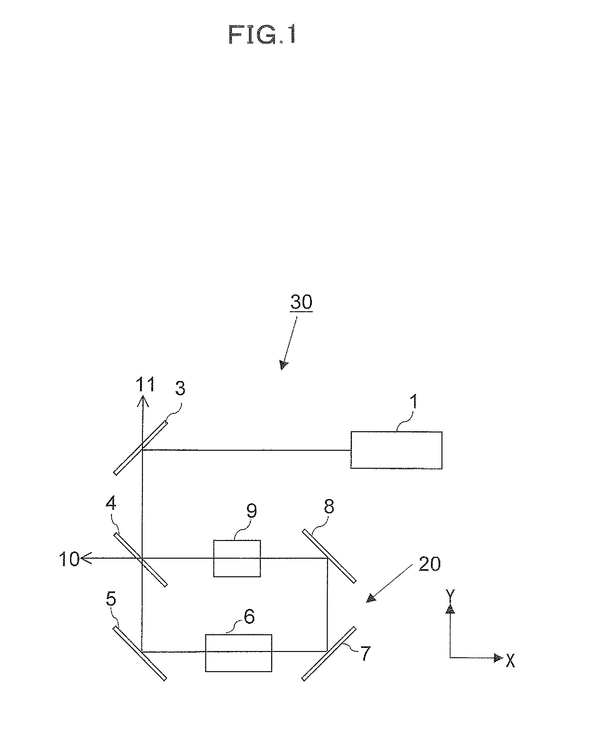
[0120]FIG. 3 is a block diagram illustrating in a plan view the makeup of the quantum entanglement generating system 40 according to the third embodiment of the present invention. Optical paths are shown in straight lines. The quantum entanglement generating system 40 shown in FIG. 2 differs from the quantum entanglement generating system 30 shown in FIG. 1 in that a ring interferometer indicated by reference character 25 is used. The makeup elsewhere is identical to that of the quantum entanglement generating system 30 whose repeated description is omitted.

[0121]The ring interferometer 25 comprises a beam splitter 4, a dispersive medium 9, a second mirror 5, an optical parametric amplifier 6 and a third mirror 7. The second mirror 5 is disposed vertically downwards (in the −Y direction) of the beam splitter 4...

first embodiment

of the Quantum Entanglement Generating and Detecting System

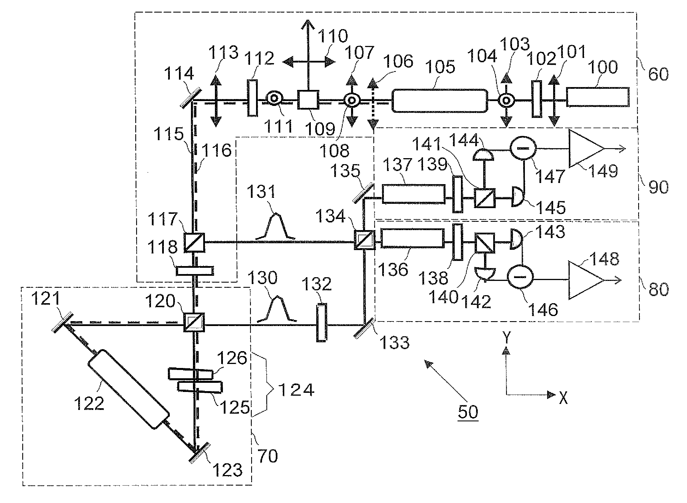
[0131]Mention is next made of a quantum entanglement generating and detecting system 50 according to a first embodiment of the present invention.

[0132]FIG. 4 is a block diagram illustrating in a plan view the makeup of a quantum entanglement generating and detecting system 50 according to its first embodiment of the present invention. Optical paths are shown in straight lines. The quantum entanglement generating and detecting system 50 is made up of a means for generating a quantum entangled beam and a means for detecting a quantum entangled beam as generated. As shown in FIG. 4, the quantum entanglement generating and detecting system 50 comprises a light source part 60, a ring interferometer 70, a first homodyne detector 80 and a second homodyne detector 90.

[0133]Here, quantum entangled beams are generated by the light source part 60 and the ring interferometer 70. Signals of quantum entangled beams as generated are detect...

second embodiment

of the Quantum Entanglement Generating and Detecting System

[0174]Mention is next made of a quantum entanglement generating and detecting system 150 according to a second form of implementation thereof in accordance with the present invention.

[0175]FIG. 5 is a block diagram illustrating in a plan view the makeup of the quantum entanglement generating and detecting system 50 according to its first form of implementation in accordance with the present invention. Optical paths are shown in straight lines. As shown in FIG. 5, the quantum entanglement generating and detecting system 150 is made up of a generating means for generating quantum entangled beams and a detecting means for detecting quantum entangled beams generated. The generating means comprises a light source part 160, a ring interferometer 170, and the detecting means comprises a first homodyne detector 180 and a second homodyne detector 190.

[0176]The light source part 160 differs from the light source part 100 in the quantu...


PUM


Abstract

A quantum entanglement generating system (30) comprises: a laser light source (1) for producing a light beam of light frequency 2f0; a ring interferometer (20) comprising a beam splitter (4) into which the light beam of light frequency 2f0 is incident and a plurality of mirrors (5, 7, 8), the beam splitter and the mirrors forming an optical path in the form of a ring; a parametric amplifier (6) inserted in the optical path of the ring interferometer for producing a beam of light of light frequency f0 upon receiving the light beam of light frequency 2f0 incident into the optical parametric amplifier; and a dispersive medium (9) inserted in the optical path of the ring interferometer for varying relative optical path length for the light beam of light frequency 2f0 and the light beam of light frequency f0, whereby two light beams of light frequency 2f0 split into at the beam splitter (4) so as to travel mutually contrariwise in direction of advance in the ring interferometer are incident into the optical parametric amplifier (6) to generate a first and a second squeezed light beam traveling mutually contrariwise in direction of advance in the ring interferometer (20), and the first and second squeezed light beams upon adjustment of their relative phase at a selected value through the dispersive medium (6) are combined in the beam splitter (4) to generate quantum entangled beams (10, 11).

Description

TECHNICAL FIELD [0001]The present invention relates to a quantum entanglement generating system and a quantum enlargement generating and detecting system and to a quantum entanglement generating method and a quantum enlargement generating and detecting method. More specifically, it relates to a system for and a method of generating quantum entanglement of continuous variables using a secondary nonlinear optical effect, and to a system that is capable of detecting generated quantum entangled beams, simultaneously with its generation as well as a method for its detection.BACKGROUND ART [0002]Quantum information techniques constitute a technology or a field of the technology that utilizes a quantum mechanical effect directly to achieve information processing performance unachievable so far. Quantum entanglement is a most important resource in the quantum information techniques. Utilization of the quantum entanglement permits actualizing absolutely safe communications and computation pr...

Claims


Application Information

Patent Timeline
IPC IPC(8): G01B9/02G02F1/39G02F1/365G02F1/37G02F1/377
CPCB82Y10/00G02F1/353G06N99/002G02F2001/392G02F2001/211G02F2201/16G06N10/00G02F1/211G02F1/392
Inventor HIRANO, TAKUYAETO, YUJIRO
Owner JAPAN SCI & TECH CORP
Why Eureka
Try Eureka