Hybrid ram air turbine with inlet guide vanes

a technology of ram air turbine and guide vanes, which is applied in the direction of machines/engines, stators, liquid fuel engines, etc., can solve the problems of insufficient power output of existing externally mounted and submerged ram air turbines, and achieve the effects of extending the surface area of the blades, enhancing the pressure differential across the blade surface, and increasing torqu

Inactive Publication Date: 2011-02-10
ADVANCED TECH GRP
View PDF9 Cites 23 Cited by
  • Summary
  • Abstract
  • Description
  • Claims
  • Application Information

AI Technical Summary

Benefits of technology

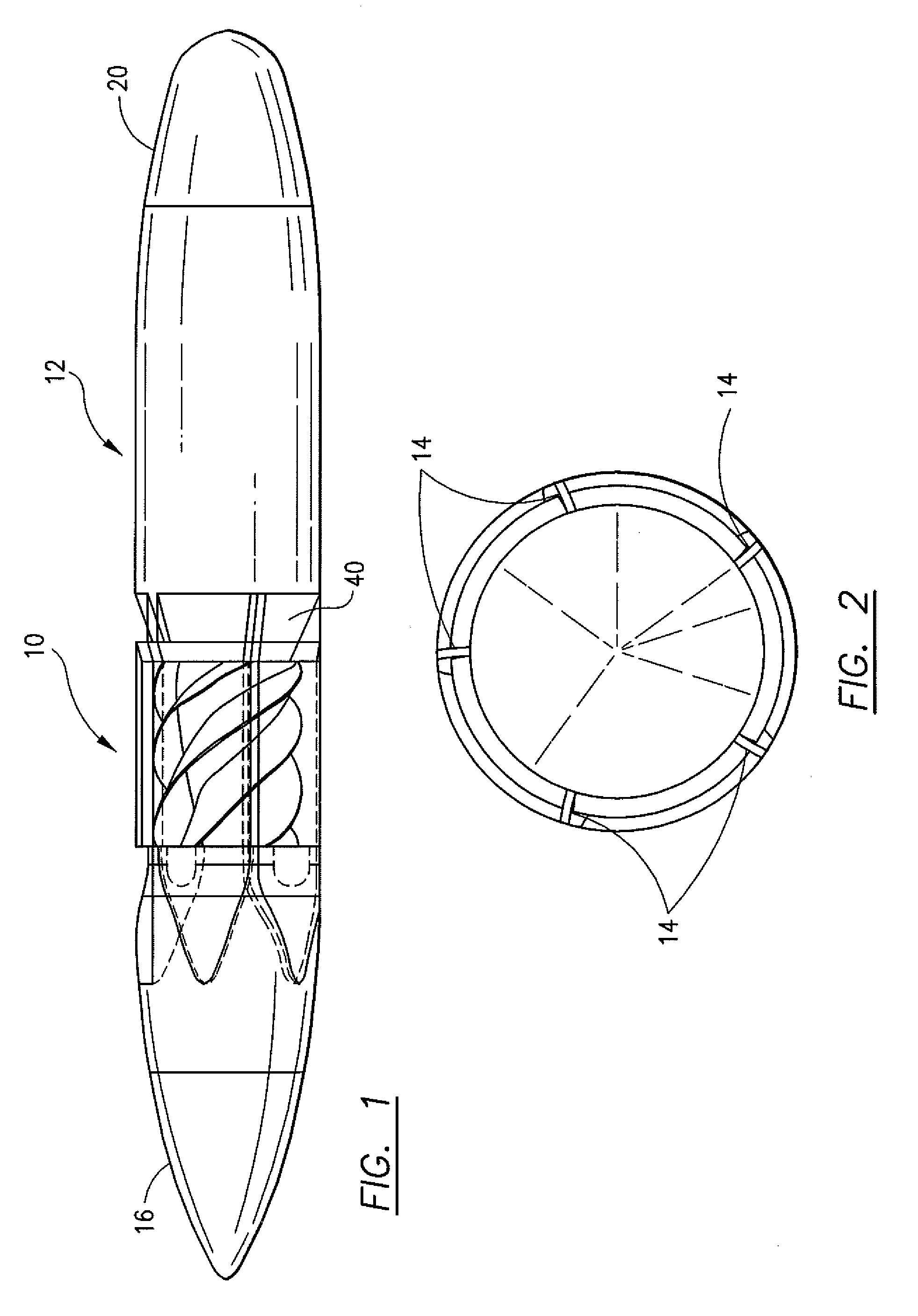
[0007]A number of features of this invention contribute to increasing the power output of the turbine herein, which, in turn, results in the generation of more electrical power than prior art designs. The orientation and shape of the inlet guide vanes not only directs flow onto the blades of the turbine, but increases pressure of the air flow at the inlet end of the pod immediately upstream from the turbine blades. The increased, axially extending surface area of the blades, as well as the blade shape, enhances the pressure differential across the blade surfaces to create increased torque. More torque translates into more power. Further, the generally conical shape of the shaft of the turbine reduces the cross sectional area between the shaft and pod wall as the air flow moves from the inlet toward the outlet of the pod, thus tending to maintain more constant pressure along the axial length of the blades which enhances the torque produced.

Problems solved by technology

Existing externally mounted and submerged ram air turbines do not provide sufficient power output, and there is a need for an improved turbine design.

Method used


Image

  • Hybrid ram air turbine with inlet guide vanes
  • Hybrid ram air turbine with inlet guide vanes
  • Hybrid ram air turbine with inlet guide vanes

Examples


Embodiment Construction

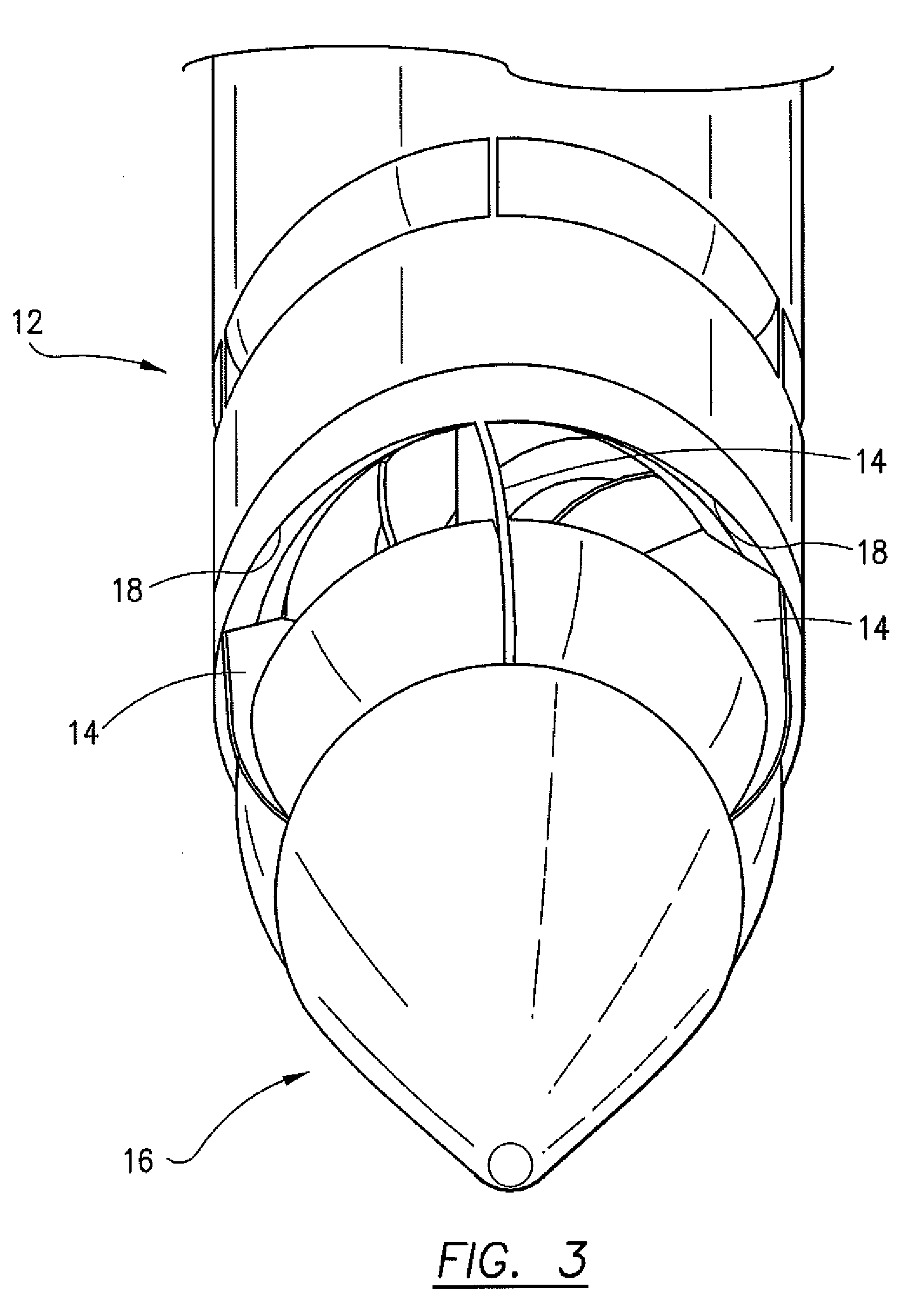
[0014]Referring now to the FIGS., the ram air turbine 10 of this invention is schematically depicted within the interior of a pod 12 of the type which can be mounted to the underside of the wing of an aircraft (not shown). A number of inlet guide vanes 14 are located at the inlet end 16 of the pod 12 in position to direct a flow of air onto the turbine 10, as discussed in detail below. The openings between adjacent guide vanes 14 define passages 18 for the flow of air produced by movement of the aircraft during flight. As best seen in FIG. 3, the guide vanes 14 are preferably formed in a wedge shape that converges toward the turbine 10 so that the cross sectional area of the passages 18 decreases in a direction from the inlet end 16 of the pod 12 toward its outlet end 20. The decrease in cross sectional area of the passages 18 reduces the velocity of the air flow stream and increases its pressure at the inlet end 16 of the pod 12.

[0015]The ram air turbine 10 comprises a shaft 22 hav...


PUM


Abstract

A hybrid ram air turbine includes a generally conical-shaped shaft which mounts a number of vanes wrapped in a substantially helical orientation along the shaft with a portion of each vane being formed in the general shape of a reaction turbine blade and another portion in the general shape of an impulse turbine blade. A number of fixed inlet guide vanes having a convergent wedge shape direct a flow of air onto the blades of the turbine which is mounted within the interior of a pod.

Description

FIELD OF THE INVENTION[0001]This invention relates to submerged ram air turbines, and, more particularly, to a hybrid submerged ram air turbine having a generally conical-shaped shaft that mounts helically wrapped blades formed with a first portion shaped like a reaction turbine blade and a second portion shaped like an impulse turbine blade wherein an air flow is directed onto the blades through a number of fixed, inlet guide vanes.BACKGROUND OF THE INVENTION[0002]Ram air turbines are commonly used in military and commercial aircraft to provide a source of hydraulic or electrical power in the event of an emergency. Modern aircraft generate power through the main engines or via an auxiliary power unit such as a fuel-burning turbine typically located in the tail of the aircraft In most applications for commercial aircraft, ram air turbines are retracted into the fuselage or wing(s) under normal operating conditions, but are deployed in the event of an emergency loss of power. They ty...

Claims


Application Information

Patent Timeline
Patent Type & Authority Applications(United States)
IPC IPC(8): F01D5/00F01D1/02
CPCB64D41/007F01D1/20F05D2250/25F02C7/32F01D15/10
Inventor JUSTAK, JOHN F.
Owner ADVANCED TECH GRP
Why Eureka
Try Eureka