
Hydrogen Generator and Fuel Pellet

a hydrogen generator and fuel pellet technology, applied in the field of hydrogen, can solve the problems of heavy weight of hydrogen storage alloy, large size, unsuitable for portable information devices, etc., and achieve the effect of enhancing electrical power output and efficient hydrogen generation

Inactive Publication Date: 2011-02-10
QINETIQ LTD
View PDF0 Cites 26 Cited by
  • Summary
  • Abstract
  • Description
  • Claims
  • Application Information

AI Technical Summary

Benefits of technology

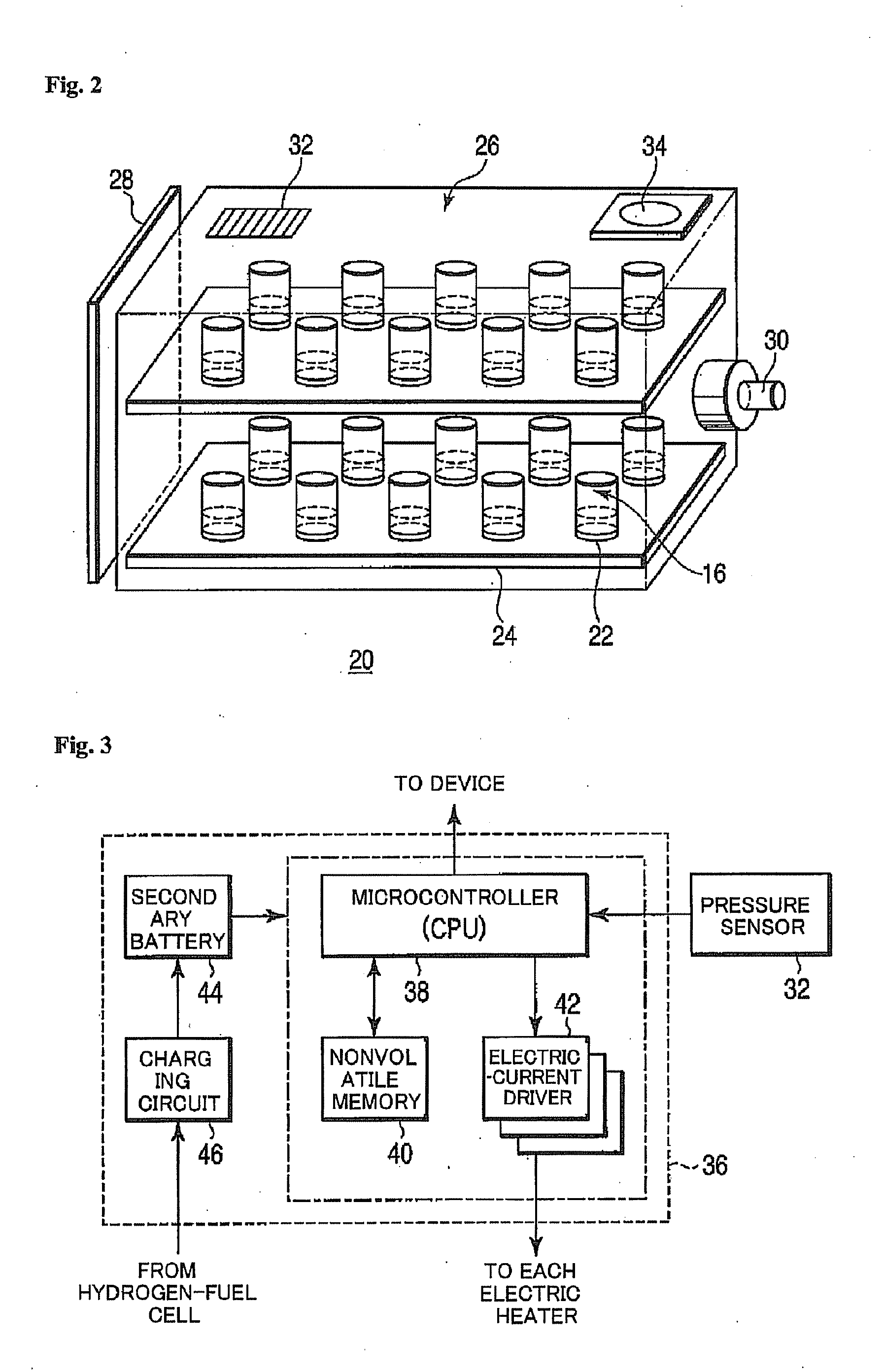
The present invention provides a hydrogen generator that can efficiently generate hydrogen from a hydrogen generating compound, even in a small size. The invention also enhances the electrical power output per unit volume of a connected hydrogen-fuel cell. The invention includes a fuel pellet body with a hydrogen generating compound compacted into a cylindrical shape and a thin plate of metal aluminum to enclose the periphery of the hydrogen generating compound. The fuel pellet is stored in a pressure-resistant container and controlled by a controller for hydrogen generation. This invention allows for efficient and reliable hydrogen generation for various applications such as fuel cells.

Problems solved by technology

However, the hydrogen storage alloy is heavy in weight, is also large in size, and accordingly is not suitable for the portable information devices.
Accordingly, there is a problem that an infrastructure for the refilling must be prepared.
However, a physical structure of the hydrogen generator described in the above described international application can be applied to a general use such as a transportable generator which can be used in the outdoor, but cannot be applied to a very small-sized hydrogen generator.
It is impossible for the structure of the above described hydrogen generator to be formed in such a size and a shape.
In addition, the above described international application does not specify various conditions for efficiently generating hydrogen in the hydrogen generator for the above described portable information devices, for instance, the specific size of ammonia borane, the environmental condition of its periphery and the like, and therefore it is impossible to realize an actual hydrogen generator.

Method used


Image

  • Hydrogen Generator and Fuel Pellet
  • Hydrogen Generator and Fuel Pellet
  • Hydrogen Generator and Fuel Pellet

Examples


first embodiment

[0025]Before a hydrogen generator according to a first embodiment of the present invention will be described, a principle of hydrogen generation will be described below.

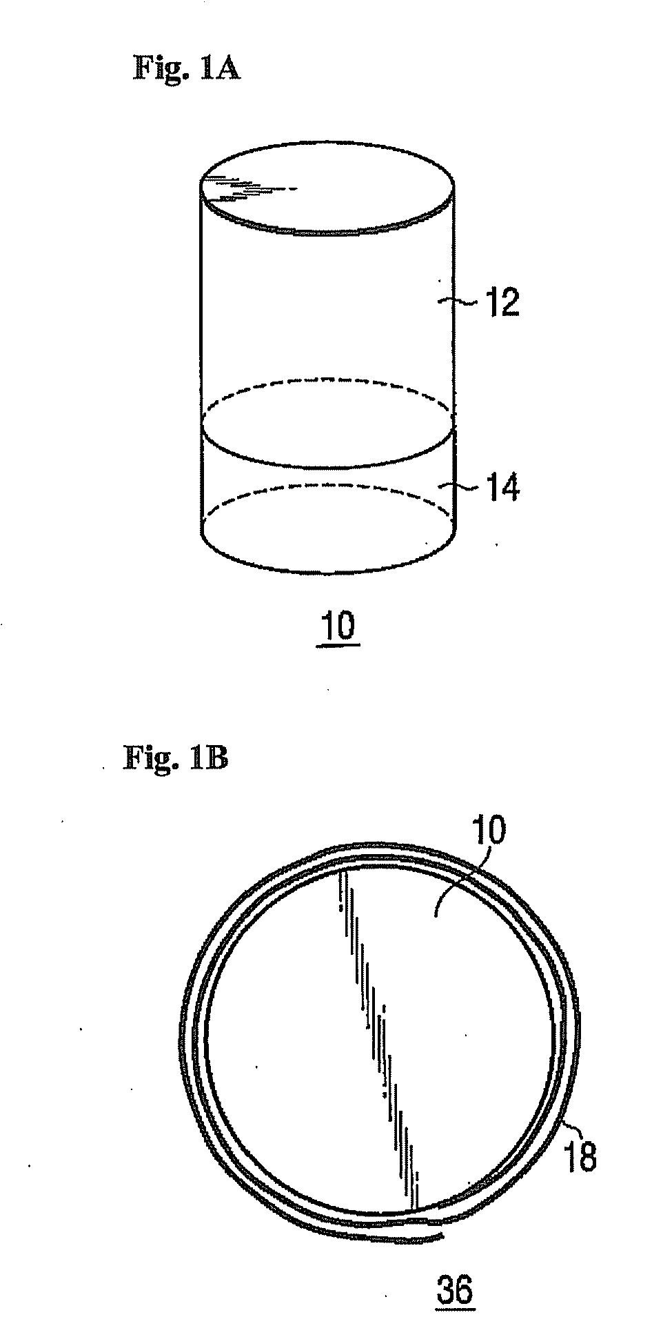
[0026]As is illustrated in FIG. 1A, a fuel pellet 10 is composed of an ammonia borane (NH3BH3) 12 which is a hydrogen generating compound, and a heat mix 14 for heating the ammonia borane 12. These ammonia borane 12 and heat mix 14 are compacted into predetermined shapes, here, cylindrical shapes, by respectively applied suitable pressures. The fuel pellet 10 is constructed by further applying a pressure to the ammonia borane 12 and the heat mix 14 so as to form an integral product.

[0027]Here, the ammonia borane 12 and the heat mix 14 will be described below.

[0028]The ammonia borane 12 contains approximately 20% hydrogen by a mass ratio, is a solid at normal temperature, has no explosibility, is a stable hydrogen source, and generates hydrogen by its thermal decomposition. The ammonia borane 12 contains twice more ma...

second embodiment

[0070]Next, the second embodiment of the present invention will be described below.

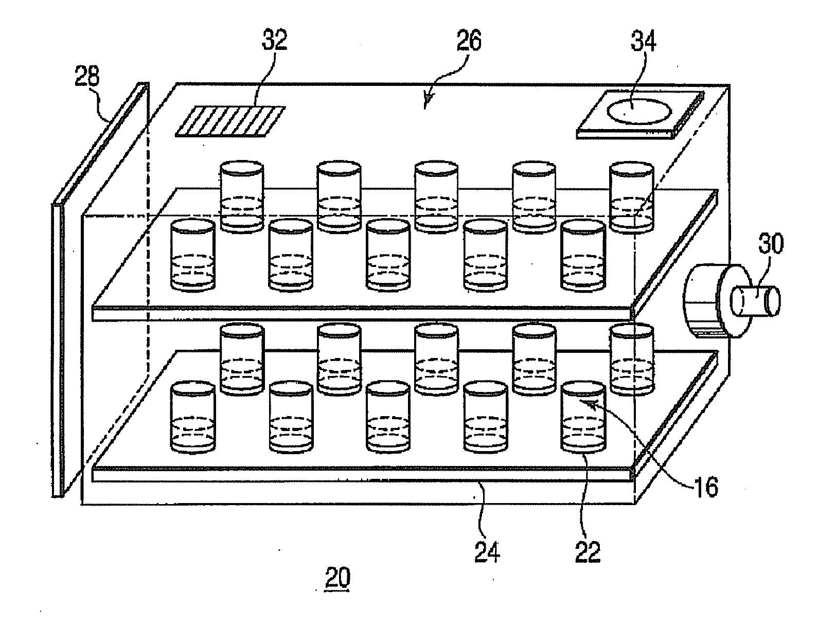
[0071]FIG. 5A is a view illustrating a sectional structure of a fuel-pellet-holding unit of a hydrogen generator 20 according to the second embodiment of the present invention. Here, the elements having the same function as in the first embodiment are denoted by the same reference numerals. In addition, note that the hatching put on the section is drawn for clarifying a difference between each member and is not intended to show such a material as is determined in Standards for drawings of The United States Patent and Trademark Office, for instance. FIG. 5B is a perspective view of the whole pellet-holding unit when overlooked from an obliquely upper part. This FIG. 5B illustrates a fuel-pellet-holding unit on which four pieces of the fuel pellet 10 as illustrated in FIG. 1A are transversely aligned and the three rows of them are longitudinally aligned, and the case in which the fuel-pellet-holding uni...


PUM

PropertyMeasurementUnit
pressureaaaaaaaaaa
pressureaaaaaaaaaa
heightaaaaaaaaaa

Abstract

A hydrogen generator comprising a plurality of a fuel pellets (10) containing a hydrogen-generating compound such as ammonia borane, a case serving as a pressure-resistant container for containing the fuel pellets, and a controller for controlling hydrogen generation from the fuel pellets. This hydrogen generator generates hydrogen from the hydrogen-generating compound by a chemical reaction. The periphery of the fuel pellet is surrounded by a member including a thin plate of metal aluminum such as aluminum foil (18) on its surface.

Description

TECHNICAL FIELD[0001]The present invention relates to a hydrogen generator which supplies hydrogen gas to a hydrogen-fuel cell for generating electric energy, and a fuel pellet body used for the same.BACKGROUND ART[0002]Portable information devices such as a cellular phone, a PDA and a digital camera has mainly used a rechargeable secondary battery like a lithium ion battery, as its power source. In recent years, along with a demand of high functions, multifunctions, speedup and a long driving time for these devices, a small-sized fuel cell is expected as a new power source, and production of a prototype or experimental use partially starts.[0003]The fuel cell is different from a conventional secondary battery, does not need a charging operation, and enables the devices to be operated for a long period of time only by replenishing the fuel or replacing a fuel cartridge. Among these fuel cells, a hydrogen-fuel cell using hydrogen as fuel can raise its power density due to its charact...

Claims


Application Information

Patent Timeline
Patent Type & Authority Applications(United States)
IPC IPC(8): B01J3/00B01J19/00G05B1/00
CPCC01B3/02C01B3/04H01M8/04037H01M8/04208Y02E60/50H01M8/04425H01M8/065Y02E60/324Y02E60/364H01M8/04216F17C11/005Y02E60/32Y02E60/36H01M8/0606
Inventor HORIGUCHI, TOSHIOMILLER, MICHAELTILSTON, JOHN
Owner QINETIQ LTD
Learn More