Hydraulic pressure supply control apparatus for automobile

a technology of hydraulic pressure supply and control apparatus, which is applied in the direction of machines/engines, engine starters, transportation and packaging, etc., can solve the problems of fuel waste in this state, and achieve the effect of avoiding the elevation of cost and increasing the complexity of configuration

Active Publication Date: 2011-02-10
TOYOTA JIDOSHA KK
View PDF2 Cites 10 Cited by
  • Summary
  • Abstract
  • Description
  • Claims
  • Application Information

AI Technical Summary

Benefits of technology

[0030]According to the present invention, a hydraulic pressure passage is provided that enables hydraulic pressure to be directly supplied to the startup friction engaging element at the time of internal combustion engine automatic stop control, and it is possible to, by closing an existing valve, suppress hydraulic oil supplied to the startup friction engaging element from flowing into the hydraulic pressure control unit including various types of valves such as a regulator valve. Accordingly, the need to newly provide a dedicated valve mechanism such as a check valve or an electromagnetic on-off valve that has been necessary in conventional technology is eliminated, and an increase in the number of parts configuring the hydraulic pressure control circuit is eliminated, and thus an increase in the complexity of the configuration and an elevation in cost can be avoided.

Problems solved by technology

When an automobile traveling in an urban area or the like stops to wait for a traffic light at an intersection or the like, the engine enters an idle running state, and fuel is wasted in this state.

Method used


Image

  • Hydraulic pressure supply control apparatus for automobile
  • Hydraulic pressure supply control apparatus for automobile
  • Hydraulic pressure supply control apparatus for automobile

Examples


embodiment 1

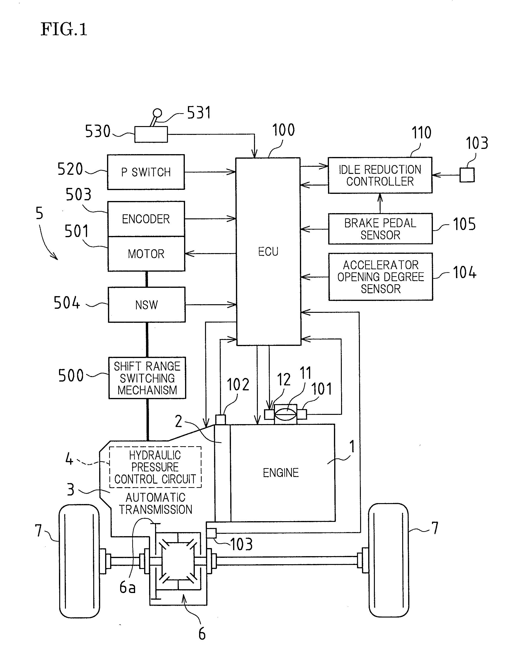
[0041]FIG. 1 is a schematic configuration diagram of a vehicle according to the present embodiment. The vehicle is an FF (front-engine, front-drive) type of vehicle, and mounted therein are an engine (internal combustion engine) 1 that is a running power source, a torque converter 2, an automatic transmission 3, a shift-by-wire system shift switching apparatus 5 that switches the shift range of the automatic transmission 3, a differential gear apparatus 6, an ECU 100, and the like.

[0042]A crankshaft (not shown) that is the output shaft of the engine 1 is coupled to the torque converter 2, and the output of the engine 1 is transmitted from the torque converter 2 to the differential gear apparatus 6 via the automatic transmission 3 and the like, and distributed to left and right drive wheels 7.

[0043]The following describes portions in the engine 1, the torque converter 2, the automatic transmission 3, the shift switching apparatus 5, and the ECU 100.

[0044]—Engine—

[0045]The engine 1 is...

embodiment 2

[0142]Next is a description of Embodiment 2. The present embodiment is a case in which a duty solenoid has been applied in place of the linear solenoid (SL1) 411. Other configurations and control are similar to those of Embodiment 1 described above, and therefore the following describes only differences from Embodiment 1.

[0143]FIG. 8 is a circuit configuration diagram showing part of a hydraulic pressure control circuit in the present embodiment.

[0144]As shown in FIG. 8, the configuration is such that a first hydraulic pressure PC1 for controlling the engagement state of the first clutch C1 is adjusted by a duty solenoid 416.

[0145]The duty solenoid 416 is configured by a three-way solenoid valve. Specifically, the duty solenoid 416 includes an input port 416a, an output port 416b, and a drain port 416c, and is capable of switching between a state in which the input port 416a and the output port 416b are in communication, and furthermore the drain port 416c is closed (the switching s...

embodiment 3

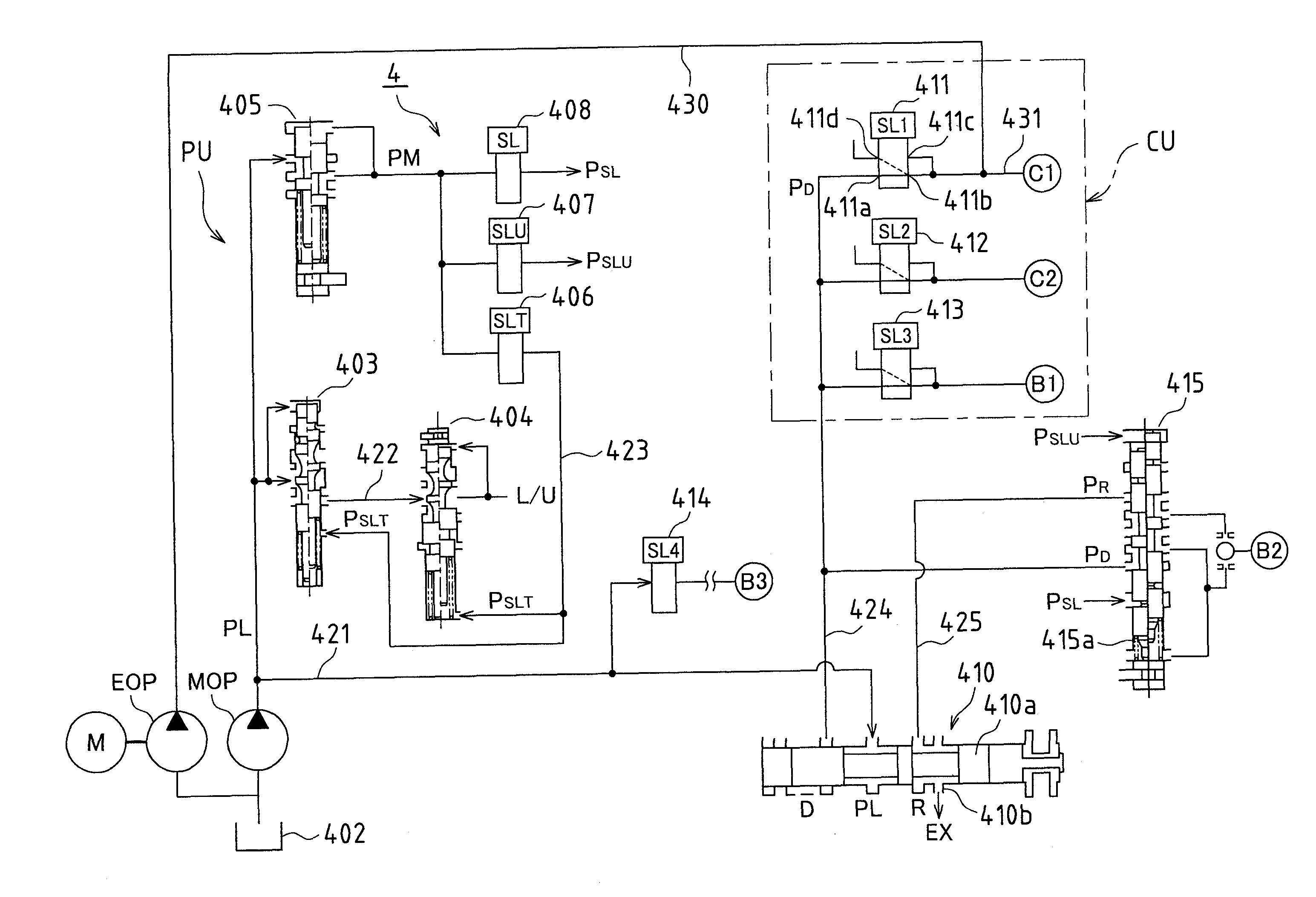
[0153]Next is a description of Embodiment 3. In the present embodiment, the manual shift valve 410 is used in order to prevent hydraulic oil supplied from the electrical oil pump EOP via the shunt hydraulic pressure supply passage 430 in the idle reduction state from flowing into the hydraulic pressure control unit PU. Other configurations and control are similar to those of Embodiment 1 described above, and therefore the following describes only differences from Embodiment 1.

[0154]The hydraulic pressure control circuit 4 of the automatic transmission 3 in the present embodiment is substantially the same as the one in Embodiment 1 described above (the one shown in FIG. 4).

[0155]In the present embodiment, when the idle reduction state described above has been entered, the spool valve 410a of the manual shift valve 410 is forcibly switched to the R range position. Accordingly, a D port connecting to the D range pressure oil passage 424 is closed, and the D range pressure oil passage 4...


PUM


Abstract

In one embodiment, a hydraulic pressure control circuit (4) of an automatic transmission includes a mechanical oil pump (MOP) and an electrical oil pump (EOP). The discharge side of the electrical oil pump (EOP) is caused to be in communication with the direct upstream side of a hydraulic pressure servo of a first clutch (C1) via a shunt hydraulic pressure supply passage (430). At the time of idle reduction, a linear solenoid (411) on the upstream side of the first clutch (C1) is caused to enter a forced closure state, thus preventing oil from the electrical oil pump (EOP) from flowing to a manual shift valve (410) side.

Description

TECHNICAL FIELD[0001]The present invention relates to a hydraulic pressure supply control apparatus for supplying hydraulic pressure to a friction engaging element in a transmission mounted in an automobile. In particular, the present invention relates to an improvement in a hydraulic pressure supply operation performed in an automobile in which an internal combustion engine (hereinafter, called the “engine”) is automatically stopped at the time of idle running of the engine.BACKGROUND ART[0002]When an automobile traveling in an urban area or the like stops to wait for a traffic light at an intersection or the like, the engine enters an idle running state, and fuel is wasted in this state. In light of this, conventionally so-called “idle reduction control” (e.g., see Patent Literature 1 to 3 below) is performed in which, if a certain condition such as the automobile stopping is established, the supply of fuel to the combustion chamber is stopped (so-called “fuel cut”), thus stopping...

Claims


Application Information

Patent Timeline
Patent Type & Authority Applications(United States)
IPC IPC(8): F02N15/00
CPCF16H2312/14Y10T477/6937Y10T477/71F16H61/686F16H61/0031B60W10/30
Inventor NAKAMURA, KAZUAKISATO, TOSHIMITSU
Owner TOYOTA JIDOSHA KK
Why Eureka
Try Eureka