
Drill burr and method for performing holes in subchondral bone to promote cartilage repair

a cartilage repair and subchondral bone technology, applied in the field of cartilage repair, can solve the problems of little scientific evidence to guide the proper implementation of microfracture, the general lack of understanding of the mechanisms and parameters that control the success versus failure of bone-marrow repair, and the failure of some patients to achieve the effect of microfractur

Inactive Publication Date: 2011-02-10
POLYVALOR LP
View PDF5 Cites 28 Cited by
  • Summary
  • Abstract
  • Description
  • Claims
  • Application Information

AI Technical Summary

Benefits of technology

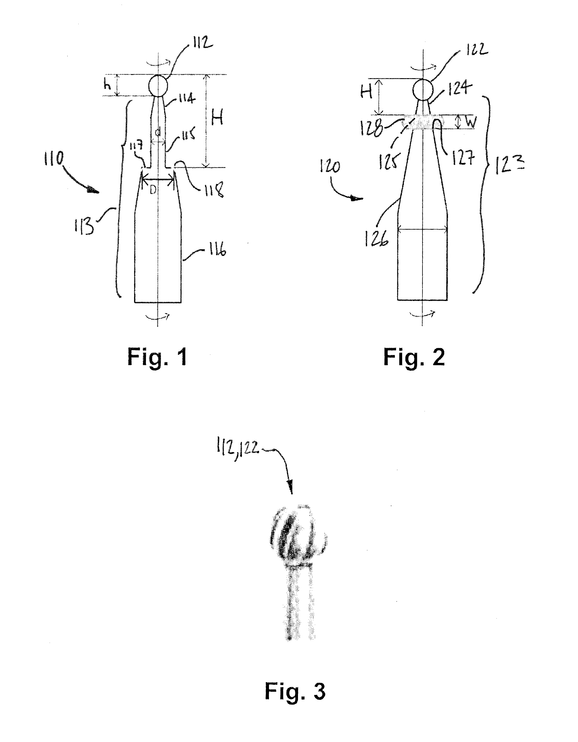
[0021]Still further in accordance with the second embodiment, the neck has a frusto-conical body between the drilling head and the stop, the frusto-conical

Problems solved by technology

Unfortunately, historical widespread and nonstandardized use of microfracture has resulted in uncontrolled and inconsistent surgical technique, follow-up measures and physiotherapy programs, and consequently there remains a lack of understanding as to why microfracture appears successful for some patients and surgeons, and not for others.
In addition, despite intrinsic differences between microfracture and the older and less favoured methods of Pridie drilling and abrasion arthroplasty, there have been no controlled animal studies, or clinical studies directly comparing these approaches to identify which features or consequences of these different methods influence their success.
Bone-marrow stimulation procedures are widely practiced in North America, but with little scientific evidence to guide their proper implementation.
There is a general lack of understanding of mechanisms and parameters that control success versus failure of bone-marrow stimulation methods for cartilage repair.
Although removal of all calcified cartilage from cartilage lesions may maximize spontaneous repair, evidence also suggests that excessive debridement which impinges too deep into subchondral bone can result in lack of repair, subchondral cysts and ultimately, poor clinical outcome, as in abrasion arthroplasty that was performed too aggressively.

Method used


Image

  • Drill burr and method for performing holes in subchondral bone to promote cartilage repair
  • Drill burr and method for performing holes in subchondral bone to promote cartilage repair

Examples


Embodiment Construction

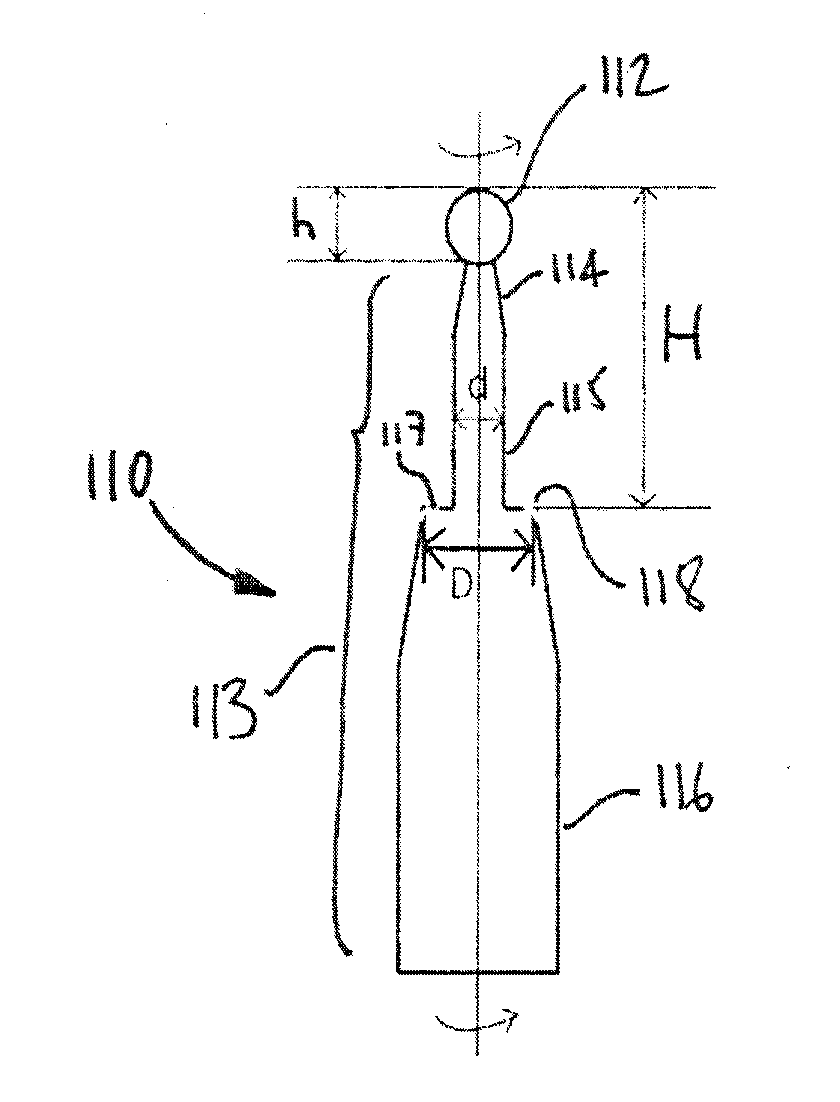
[0032]Referring to FIG. 1, a drill burr in accordance with a first embodiment is generally shown at 110. The drill burr 110 is used to drill holes through cartilage zones and calcified cartilage so as to reach the subchondral bone, to promote bone marrow stimulation for cartilage repair.

[0033]The drill burr 110 has a drilling head 112. As an example, the drilling head 112 has a diameter “h” of approximately 0.9 mm, and is shown in greater detail in FIG. 3.

[0034]The drilling head 112 is connected to the drill by way of a neck 113. The neck 113 has, amongst other parts, a frustoconical portion 114, a cylindrical portion 115, and a connector portion 116. The frusto-conical portion 114 is connected to the drilling head 112. The frustoconical portion 114 provides an irrigation space during drilling to avoid overheating the periphery of the hole, so as to reduce the risk of cell necrosis. Other configurations are considered in the neck 113 to provide irrigation during drilling.

[0035]The c...


PUM


Abstract

A method for performing holes in subchondral bone to promote cartilage repair comprises selecting a drill burr having a drilling head and an axial stop, as a function of the distance between the tip of the drilling head and the axial stop and of a desired depth to reach a desired subchondral bone marrow compartment of a patient; drilling a hole through a base of a cartilage lesion with the drill burr to reach the desired subchondral bone marrow compartment of the patient; abutting the base of the cartilage lesion defining a periphery of the hole with the axial stop while drilling; and withdrawing the drill burr from the hole; whereby the hole has the desired depth and reaches the desired subchondral bone marrow compartment to promote cartilage repair.

Description

CROSS-REFERENCE TO RELATED APPLICATION[0001]This patent application claims priority on U.S. Provisional Patent Application No. 61 / 032,610, filed on Feb. 29, 2008.FIELD OF THE APPLICATION[0002]The present application relates to cartilage repair and, more particularly, to a surgical tool and to a method for stimulating bone marrow to promote cartilage repair.BACKGROUND OF THE ART[0003]Adult articular cartilage is composed of three stratified layers with distinct morphological characteristics, namely the superficial zone, the transitional zone and the radial zone. The superficial zone includes the articulating surface and contains chondrocytes with a discoidal morphology, a tangential orientation of collagen fibrils. The transitional zone, below the superficial zone, contains chondrocytes with a rounder morphology and displays a more isotropic orientation of collagen. The bulk of adult articular cartilage lies in the deepest zone, or radial zone, named to depict the radiating pattern o...

Claims


Application Information

Patent Timeline
IPC IPC(8): A61B17/16
CPCA61B2019/306A61B17/1615A61B2090/036
Inventor BUSCHMANN, MICHAEL D.CHEN, HONGMEI
Owner POLYVALOR LP
Learn More