Waste processing system

a technology of processing system and waste, applied in the direction of combined combustion mitigation, combustion process, lighting and heating apparatus, etc., can solve the problems of social inacceptability of the process and limited waste management solutions

Inactive Publication Date: 2011-02-17
ETHOS ENERGY WORLDWIDE LTD
View PDF15 Cites 14 Cited by
  • Summary
  • Abstract
  • Description
  • Claims
  • Application Information

AI Technical Summary

Benefits of technology

[0018]Small footprint, easily integrated into existing premises and existing services.

Problems solved by technology

Therefore, in smaller local applications, waste management solutions are more limited.
Incineration is a common method of waste destruction / reduction in larger applications, however, such a process has become socially unacceptable due to a large footprint (both carbon footprint and physical space required), high profile, potential for air and water pollution, and reliance on vehicles with associated emissions and CO2.

Method used


Image

  • Waste processing system
  • Waste processing system
  • Waste processing system

Examples


Embodiment Construction

)

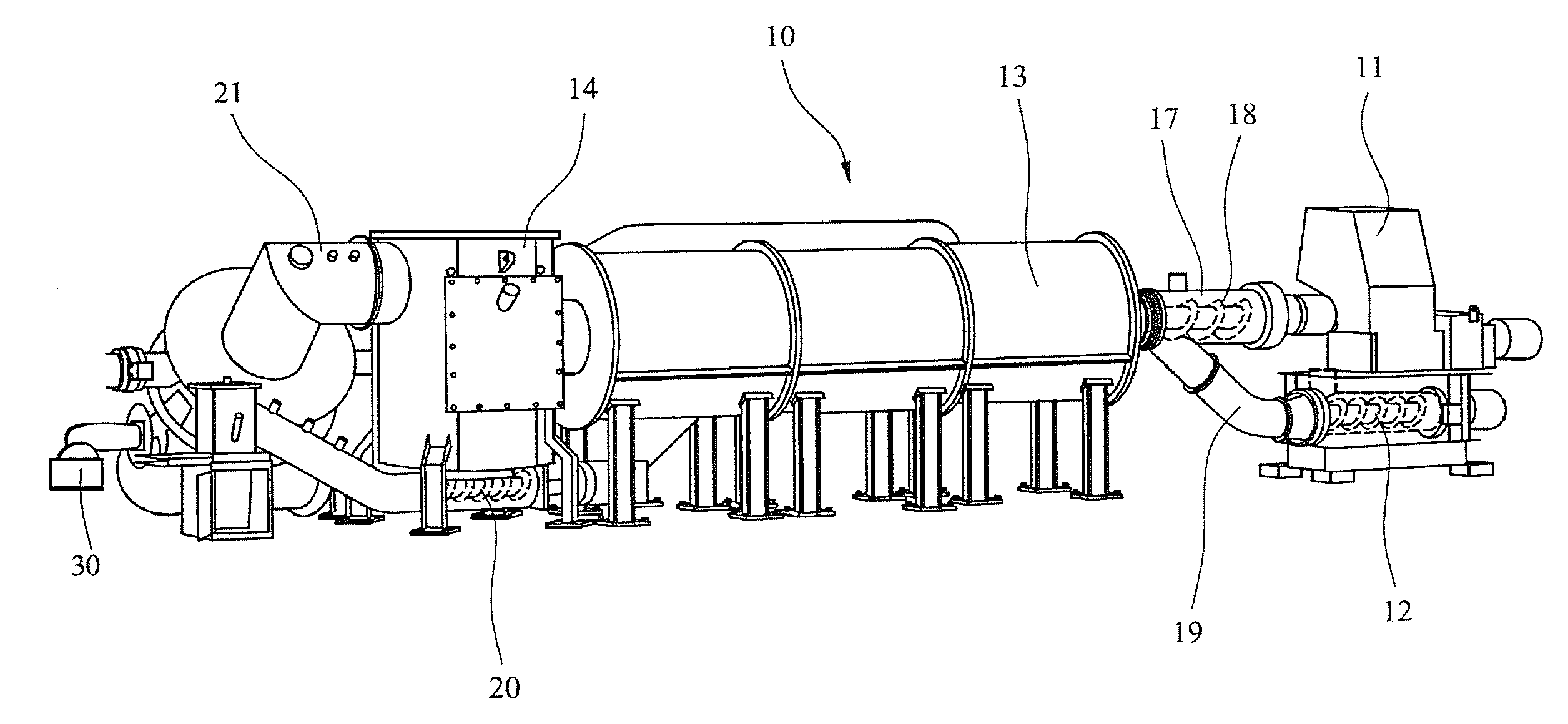
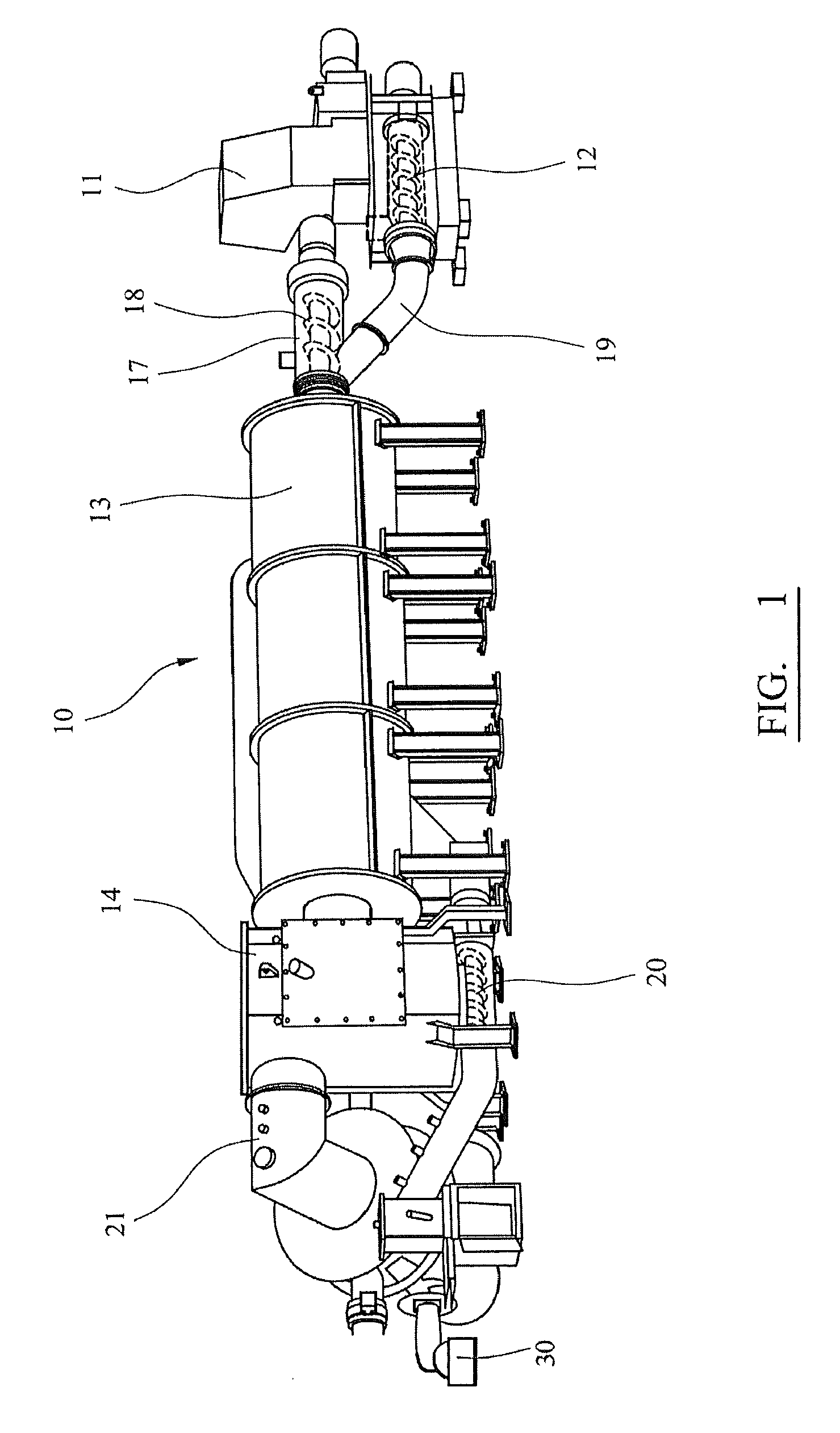
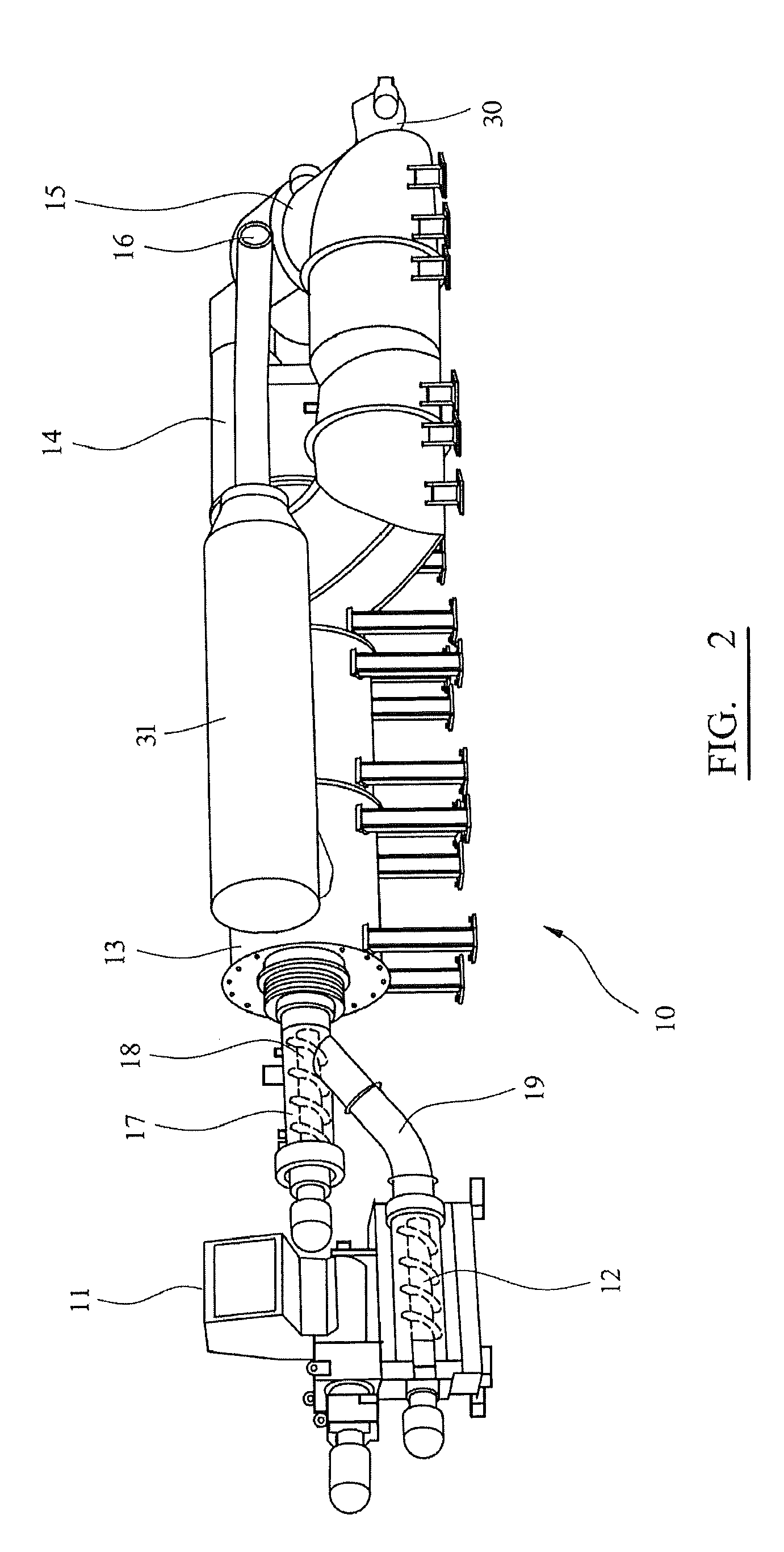
[0025]FIGS. 1 and 2 illustrate an external view of the components of a waste processing system according to the invention. The apparatus 10 includes a shredder 11, a compactor 12, a pyrolyser 13, a gasifier / ash vessel 14, an oxidiser 15, a heat reclaimer 31 and an outlet flue 16. Each stage of the system is discussed in detail below.

[0026]As a pre-feed treatment, the waste is processed through the shredder 11 to homogenize it and act as a separator for contaminants, mainly consisting of materials that may be injurious to mechanical handling.

[0027]The greater the homogeneity of the waste feed, the smoother the operation of the thermal plant, leading to increased processing capacity of the plant and increased life of the components. Preferably, before entering the shredder 11, large items and other damaging materials are removed. Separation may be performed by hand or automated depending on the application and available manual resources.

[0028]Size reduction of the waste has an added ...


PUM


Abstract

A small scale integrated waste processing system for the thermal destructions of waste. The system comprises a compactor (12) for densifying waste and expressing air, a pyrolyzer (13) to receive waste delivered from the compactor, a gasifier (14) with an ash vessel (23) that receives dried waste, and an oxidizer (15) receiving gas from the gasifier to be combusted. Heat energy from the oxidizer can be routed back to the pyrolyzer.

Description

CROSS REFERENCE TO RELATED APPLICATION[0001]This application is based on provisional application Ser. No. 61 / 233,239, filed Aug. 12, 2009, all of the details of which are incorporated herein by reference thereto.BACKGROUND OF THE INVENTION[0002]The present invention relates to a waste processing system.[0003]Modern methods for the thermal destruction of waste, to meet environmental standards, are usually conducted on a large scale to be economical and safe. Therefore, in smaller local applications, waste management solutions are more limited. Incineration is a common method of waste destruction / reduction in larger applications, however, such a process has become socially unacceptable due to a large footprint (both carbon footprint and physical space required), high profile, potential for air and water pollution, and reliance on vehicles with associated emissions and CO2.[0004]An example of a situation where smaller scale thermal destruction is desirable is on board an ocean going sh...

Claims


Application Information

Patent Timeline
Patent Type & Authority Applications(United States)
IPC IPC(8): F23G5/00
CPCF23G5/027F23G5/033F23G5/46F23G5/50F23G2201/303F23G2201/304Y02E20/12F23G2201/603F23G2201/80F23G2206/10F23G2206/202F23G2206/203F23G2900/50209F23G2201/40
Inventor TOASE, BRUCESWEETING, DAVIDEDMONDSON, SCOTT
Owner ETHOS ENERGY WORLDWIDE LTD
Why Eureka
Try Eureka