Variable Feature Interface That Induces A Balanced Stress To Prevent Thin Die Warpage

a technology of feature interface and stress, which is applied in the field of manufacturing integrated circuits, can solve the problems of loss of time and resources, loss of structural strength of first die, and insufficient mechanical strength of thin die, and achieve the effect of preventing warpage during semiconductor assembly

Inactive Publication Date: 2011-02-17
QUALCOMM INC
View PDF5 Cites 26 Cited by
  • Summary
  • Abstract
  • Description
  • Claims
  • Application Information

AI Technical Summary

Benefits of technology

[0009]According to one aspect of the disclosure, a semiconductor system includes a semiconductor die having an interconnect structure with elements of at least one variable feature. The variable features allows for opposite bending on the semiconductor die to mitigate warpage during semiconductor assembly. The semiconductor system also includes a first packaging substrate that communicates with the semiconductor die through the interconnect structure.
[0010]According to another aspect of the disclosure, a method of semiconductor assembly includes providing on a semiconductor die an interconnect structure having elements of a variable feature. The elements of variable feature allow a reverse bend on the semiconductor die during the semiconductor assembly. The reverse bend mitigates warpage during the semiconductor assembly. The method also includes coupling the semiconductor die to a packaging substrate through the interconnect structure.
[0011]According to a further aspect of the disclosure, a semiconductor system includes a packaging substrate. The semiconductor system also includes a semiconductor die coupled to the packaging substrate through means for communicating with the packaging substrate. The communicating means having elements of at least one variable feature. The variable feature allows a reverse bend on the semiconductor die to mitigate warpage of the semiconductor die during semiconductor assembly.

Problems solved by technology

During these transfers the semiconductor die can break, resulting in a loss of time and resources.
As the height of the first die decreases to accommodate the through silicon via manufacturing, the first die loses structural strength.
The bending results from insufficient mechanical strength of the thin die to withstand heat cycles and thermal mechanical changes during the assembly process.
Bending of the thin die may result in broken or undesirable function of components in the thin die.
Additionally, physical bending may result in an undesirable semiconductor die geometry or size.

Method used


Image

  • Variable Feature Interface That Induces A Balanced Stress To Prevent Thin Die Warpage
  • Variable Feature Interface That Induces A Balanced Stress To Prevent Thin Die Warpage
  • Variable Feature Interface That Induces A Balanced Stress To Prevent Thin Die Warpage

Examples


first embodiment

[0033]FIG. 5 is a block diagram illustrating an exemplary packaged die having induced reverse bending according to a A packaged die 500 includes a packaging substrate 510 having a packaging connection 520. Coupled to the packaging substrate 510 is a die 540. The die 540 is coupled to the packaging substrate 510 through an interconnect structure 530. The interconnect structure 530 may be, for example, bumps or pillars.

[0034]A reverse bending of the die 540 occurs during reflow of the interconnect structure 530 (and / or during compression of the die 540 towards the packaging substrate 510) by varying a height of the interconnect structure components (e.g., bumps or pillars). When the die 540 is compressed against the packaging substrate 510 the die 540 bends. Bending of the die 540 in one embodiment is designed to induce an inverse bend resulting from an inverse stress to counter bending imposed by a heating and cooling process such as reflow. A controlled inverse bend may be engineer...

second embodiment

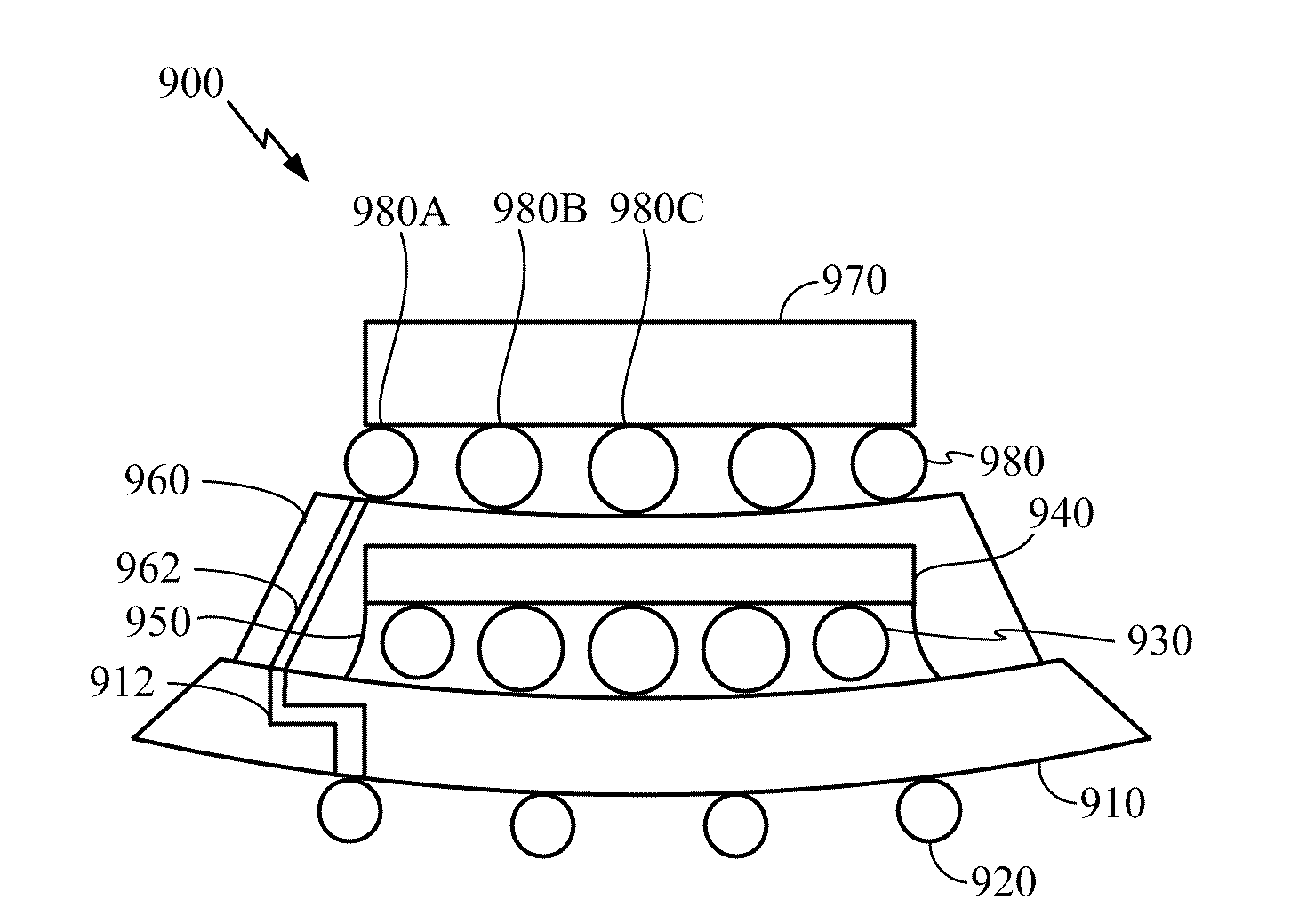
[0044]Another example of balancing bending in a semiconductor die by inducing a reverse bending is now explained with reference to FIG. 7 and FIG. 8. FIG. 7 is a block diagram illustrating an exemplary packaged die having induced reverse bending according to a A packaged die 700 includes a packaging substrate 710 having a packaging connection 720. Coupled to the packaging substrate 710 is a die 740. The die 740 is coupled to the packaging substrate 710 through an interconnect structure 730. The interconnect structure 730 may be bumps of a ball grid array or solder pillars, for example.

[0045]A reverse bend may be induced through the interconnect structure 730 by varying a height of the interconnect structure 730 corresponding to location relative to the die 740. For example, if the interconnect structure 730 is bumps of a ball grid array, the height of each bump is varied. A bump 730A at the periphery of the die 740 is smaller than a bump 730B closer to the center of the die 740. Th...


PUM


Abstract

A packaged semiconductor product includes a packaging substrate coupled to a semiconductor die through an interconnect structure with elements of variable features. The interconnect structure may be bumps or pillars. The variable features of the interconnect structure induce a reverse bend on the semiconductor die that mitigates warpage of the semiconductor die during semiconductor assembly by balancing bending of the packaging substrate during reflow. The variable features can be variable height and / or variable composition.

Description

TECHNICAL FIELD[0001]The present disclosure generally relates to integrated circuits (ICs). More specifically, the present disclosure relates to manufacturing integrated circuits.BACKGROUND[0002]Semiconductor dies include collections of transistors and other components. Commonly, these substrates are semiconductor materials, and, in particular, silicon. Additionally, these substrates are conventionally thicker than necessary to obtain desirable device behavior. The semiconductor dies are singulated or diced from a semiconductor wafer.[0003]Thick dies have advantages during semiconductor assembly. During assembly of semiconductor dies such as packaging, a semiconductor die endures dozens of processes, high temperatures, and transfers between tools or even fabrication sites. During these transfers the semiconductor die can break, resulting in a loss of time and resources. Thick dies are less likely to be damaged during manufacturing.[0004]Despite the advantages of thick dies listed ab...

Claims


Application Information

Patent Timeline
Patent Type & Authority Applications(United States)
IPC IPC(8): H01L23/48H01L21/768H01L23/488
CPCH01L21/563H01L23/3128H01L2225/1058H01L2225/1023H01L2224/73204H01L2224/32225H01L2224/16145H01L2924/014H01L2924/01047H01L2924/01033H01L2924/3511H01L2924/15311H01L2924/14H01L2924/01078H01L2924/01029H01L2225/06555H01L2225/06541H01L2225/06517H01L23/49816H01L23/562H01L24/14H01L24/17H01L24/81H01L25/0657H01L25/105H01L25/50H01L2224/0401H01L2224/0603H01L2224/06505H01L2224/13099H01L2224/13147H01L2224/1403H01L2224/14505H01L2224/16225H01L2224/812H01L2224/81801H01L2224/83102H01L2224/92125H01L2225/06513H01L2924/00H01L2924/00012H01L2924/181H01L2224/1703H01L2224/14
Inventor CHANDRASEKARAN, ARVINDRADOJCIC, RATIBOR
Owner QUALCOMM INC
Why Eureka
Try Eureka