
Concentrated winding machines with reduced torque ripple and methods for designing the same

a winding machine and torque ripple technology, applied in the direction of magnetic circuit rotating parts, magnetic circuit shape/form/construction, instruments, etc., can solve the problems of unwanted vibration and noise, increase cost, and manufacturing complexity

Inactive Publication Date: 2011-02-17
GM GLOBAL TECH OPERATIONS LLC
View PDF21 Cites 13 Cited by
  • Summary
  • Abstract
  • Description
  • Claims
  • Application Information

AI Technical Summary

Benefits of technology

[0006]This summary is provided to introduce a selection of concepts in a simplified form that are further described below in the detailed description. This summary is not intended to identify key features or essential features of the claimed subject matter, nor is it intended to be used as an aid in determining the scope of the claimed subject matter.

Problems solved by technology

Permanent magnet motors may produce undesirable torque ripple that may result in unwanted vibration and noise.
However, skewing may introduce manufacturing complexity and increase cost.
Skewing may also lower machine torque, and thus, lower machine performance.

Method used


Image

  • Concentrated winding machines with reduced torque ripple and methods for designing the same
  • Concentrated winding machines with reduced torque ripple and methods for designing the same
  • Concentrated winding machines with reduced torque ripple and methods for designing the same

Examples


Embodiment Construction

[0012]The following detailed description is merely illustrative in nature and is not intended to limit the embodiments of the subject matter or the application and uses of such embodiments. As used herein, the word “exemplary” means “serving as an example, instance, or illustration.” Any implementation described herein as exemplary is not necessarily to be construed as preferred or advantageous over other implementations. Furthermore, there is no intention to be bound by any expressed or implied theory presented in the preceding technical field, background, brief summary or the following detailed description.

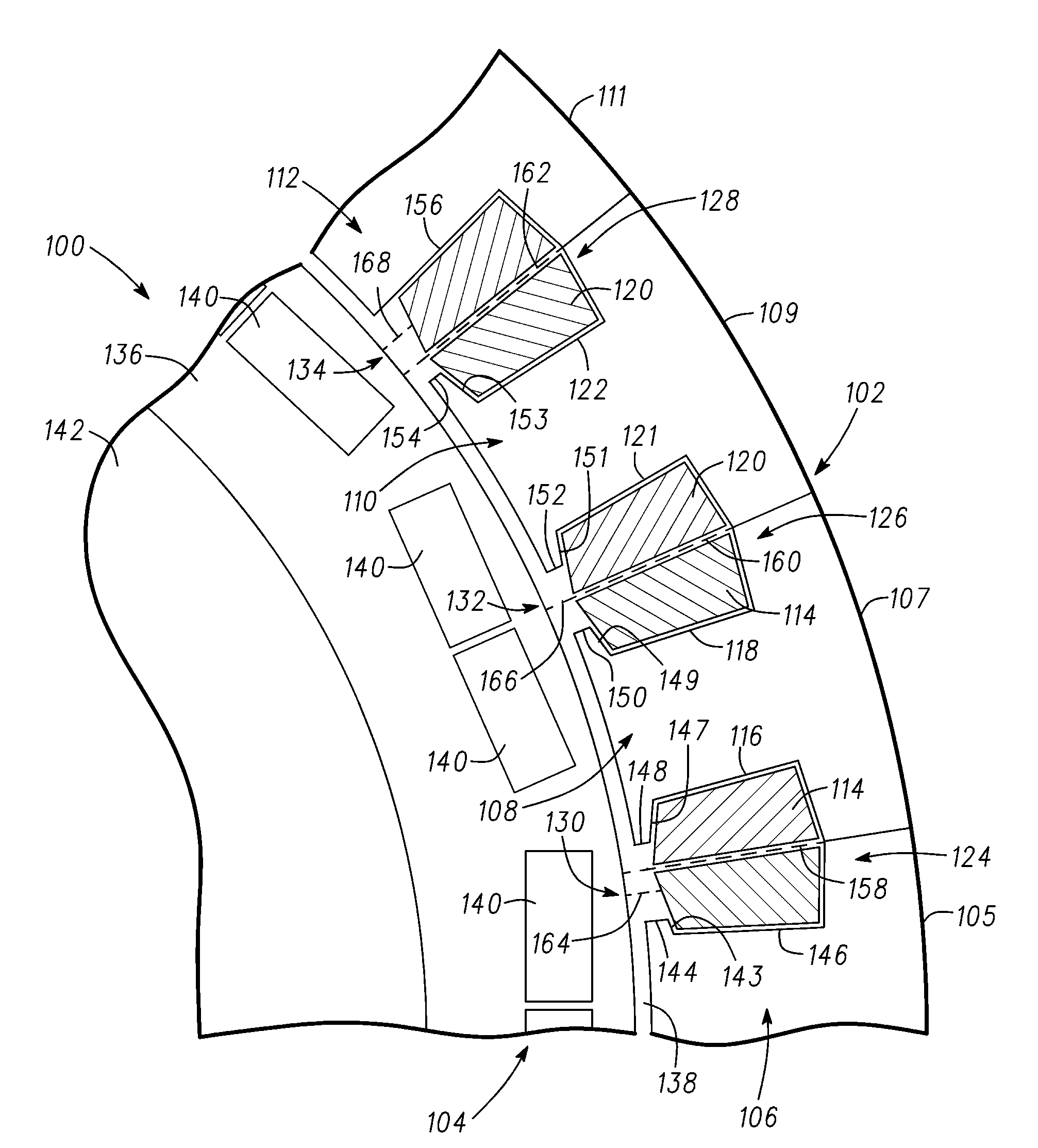
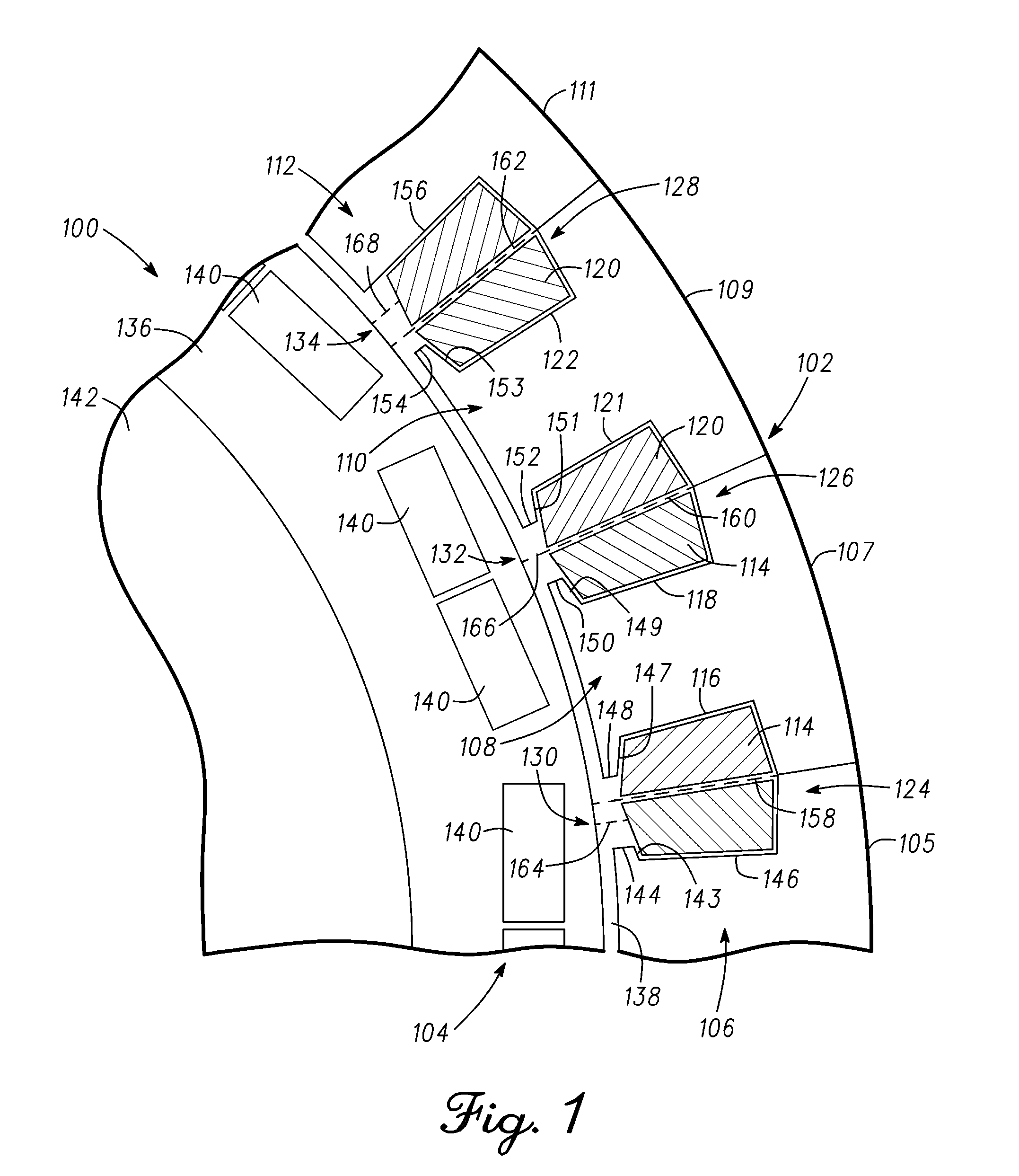
[0013]FIG. 1 depicts a partial cross-sectional view of a permanent magnet motor 100 in accordance with an exemplary embodiment. The view of FIG. 1 represents ⅛th of a complete cross-sectional view of the motor 100. In an exemplary embodiment, the motor 100 includes a stator 102 and a rotor 104 rotatably disposed within the stator 102. The motor 100 may form parts of various auto...


PUM


Abstract

Systems and methods are provided for a motor having a concentrated winding construction with reduced torque ripple. A motor comprises a stator including a plurality of tooth segments disposed circumferentially to establish a hollow core and a rotor rotatably disposed inside the hollow core. The plurality of tooth segments define a plurality of slot openings associated with a plurality of slots. Each slot of the plurality of slots has a slot opening and at least one slot opening of the plurality of slot openings is asymmetric with respect to the plurality of slot openings.

Description

TECHNICAL FIELD[0001]Embodiments of the subject matter described herein relate generally to electric motors, and more particularly relate to concentrated winding machines with reduced torque ripple.BACKGROUND[0002]Permanent magnet motors may produce undesirable torque ripple that may result in unwanted vibration and noise. Conventional permanent magnet motors skew either the rotor or the stator in an attempt to reduce the torque ripple. However, skewing may introduce manufacturing complexity and increase cost. Skewing may also lower machine torque, and thus, lower machine performance.BRIEF SUMMARY[0003]In accordance with one embodiment, an apparatus is provided for a motor. The motor comprises a stator including a plurality of tooth segments disposed circumferentially to establish a hollow core and a rotor rotatably disposed inside the hollow core. The plurality of tooth segments define a plurality of slot openings associated with a plurality of slots. Each slot of the plurality of ...

Claims


Application Information

Patent Timeline
Patent Type & Authority Applications(United States)
IPC IPC(8): H02K1/16G06F17/50G06G7/63H02K15/02
CPCH02K1/148H02K1/165Y10T29/49009Y02T10/82H02K29/03
Inventor RAHMAN, KHWAJA M.LABA, MATTHEW D.KAISER, EDWARD L.SAVAGIAN, PETER J.
Owner GM GLOBAL TECH OPERATIONS LLC
Learn More