

Distributed Beacon Enabled Wireless Networks
- Summary
- Abstract
- Description
- Claims
- Application Information
AI Technical Summary
Benefits of technology
Problems solved by technology
Method used
Image

Examples
Embodiment Construction
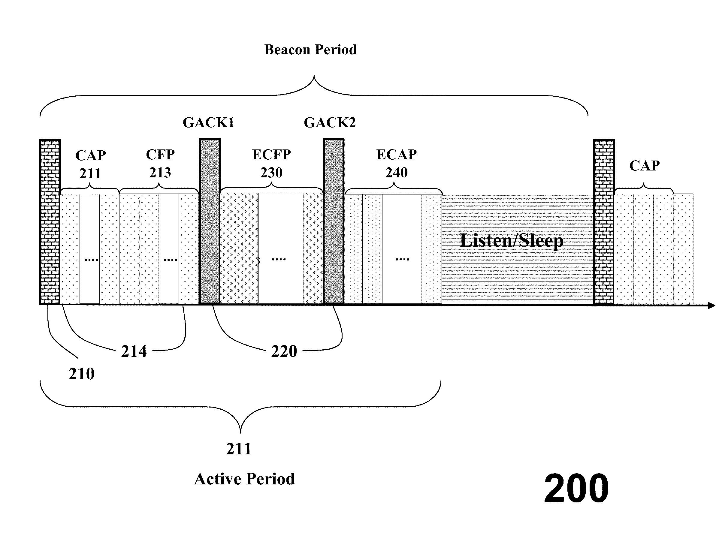
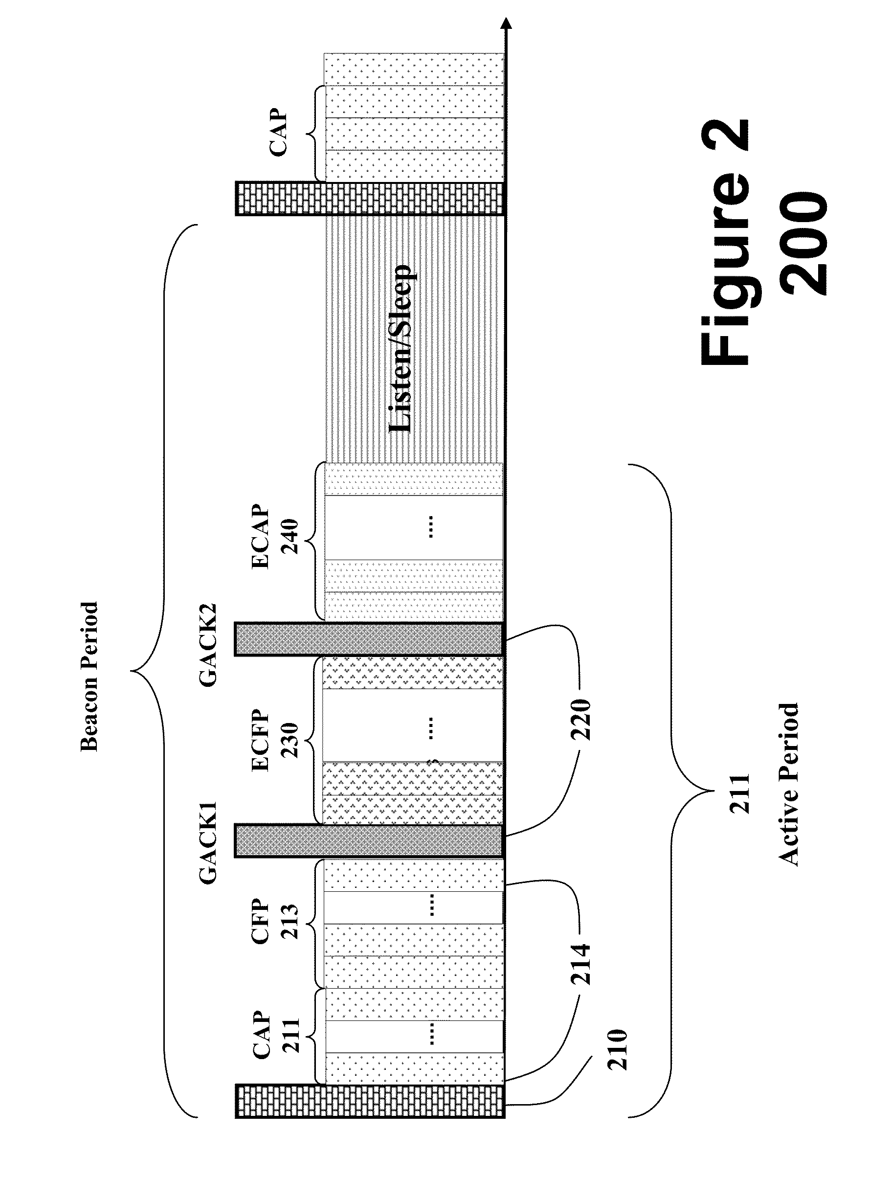
[0033]The embodiments of our invention provide a protocol that operates in a distributed manner in a network of transceiver nodes, and offers an automatic resource management mechanism that is distributed in its nature, and scalable. The protocol uses period announcement cycles to specify a communication schedule for the nodes.
[0034]The network offers a very reliable communication services. It offers low latency by providing opportunities for retransmission of failed data frames in the same super frame. It offers a certain degree of determinism in the sense that data frame will be delivered in the same super frame. That is, the super frame duration defines maximum transmission delay for one hop transmission. The network is adaptive to burst traffic in the sense that the nodes having unusual data arrivals can request for additional bandwidth from a coordinator node. This bandwidth is dynamically allocated in the same super frame. The protocol does not require assistance from higher l...
PUM
 Abstract
Description
Claims
Application Information