
Coherent receiver having an interleave-chirped arrayed waveguide grating

a receiver and waveguide technology, applied in the field of optical communication equipment, can solve the problems of relatively large corresponding receivers, and relatively high optical attenuation

Active Publication Date: 2011-02-17
ALCATEL LUCENT SAS
View PDF6 Cites 88 Cited by
  • Summary
  • Abstract
  • Description
  • Claims
  • Application Information

AI Technical Summary

Benefits of technology

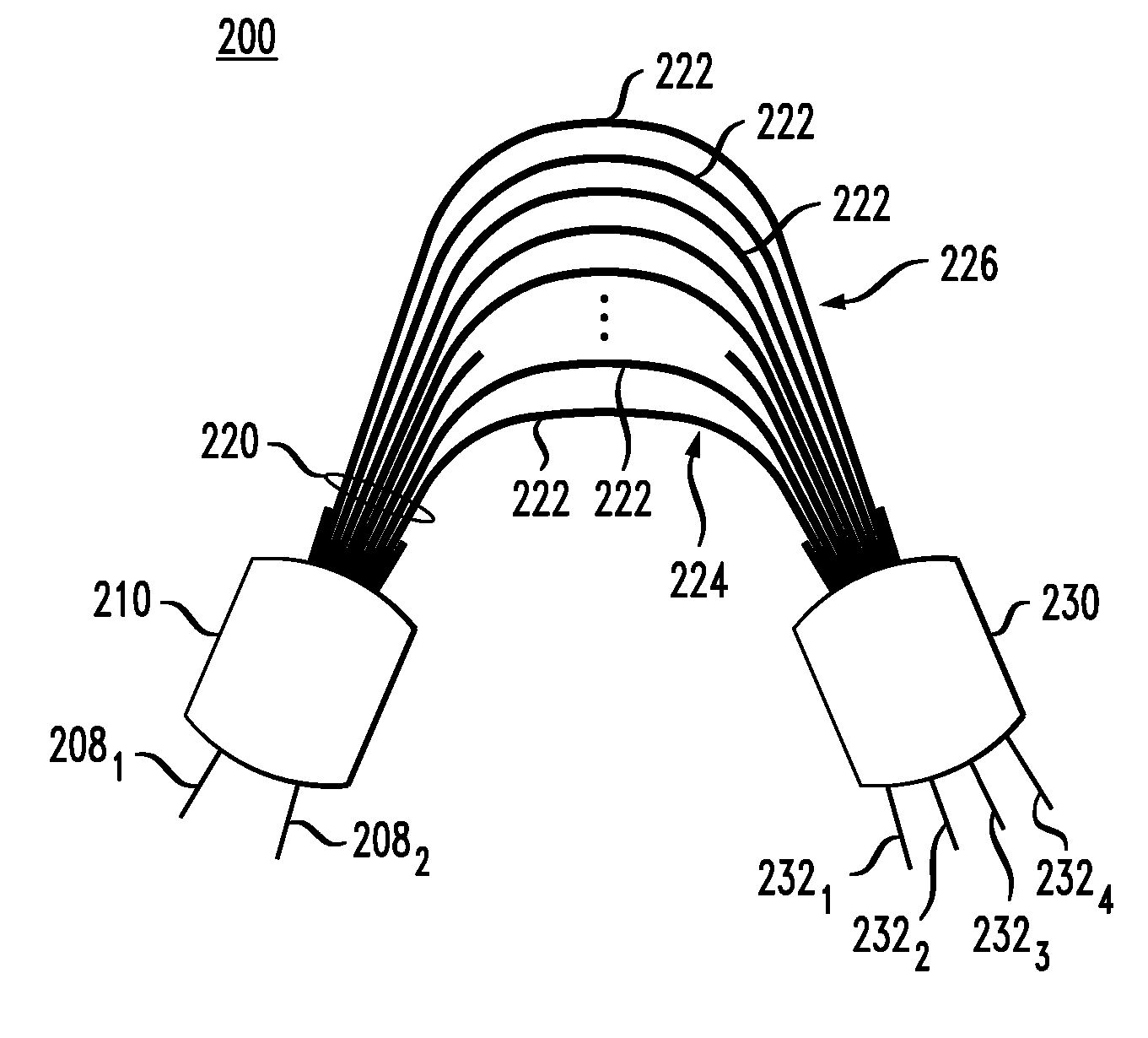
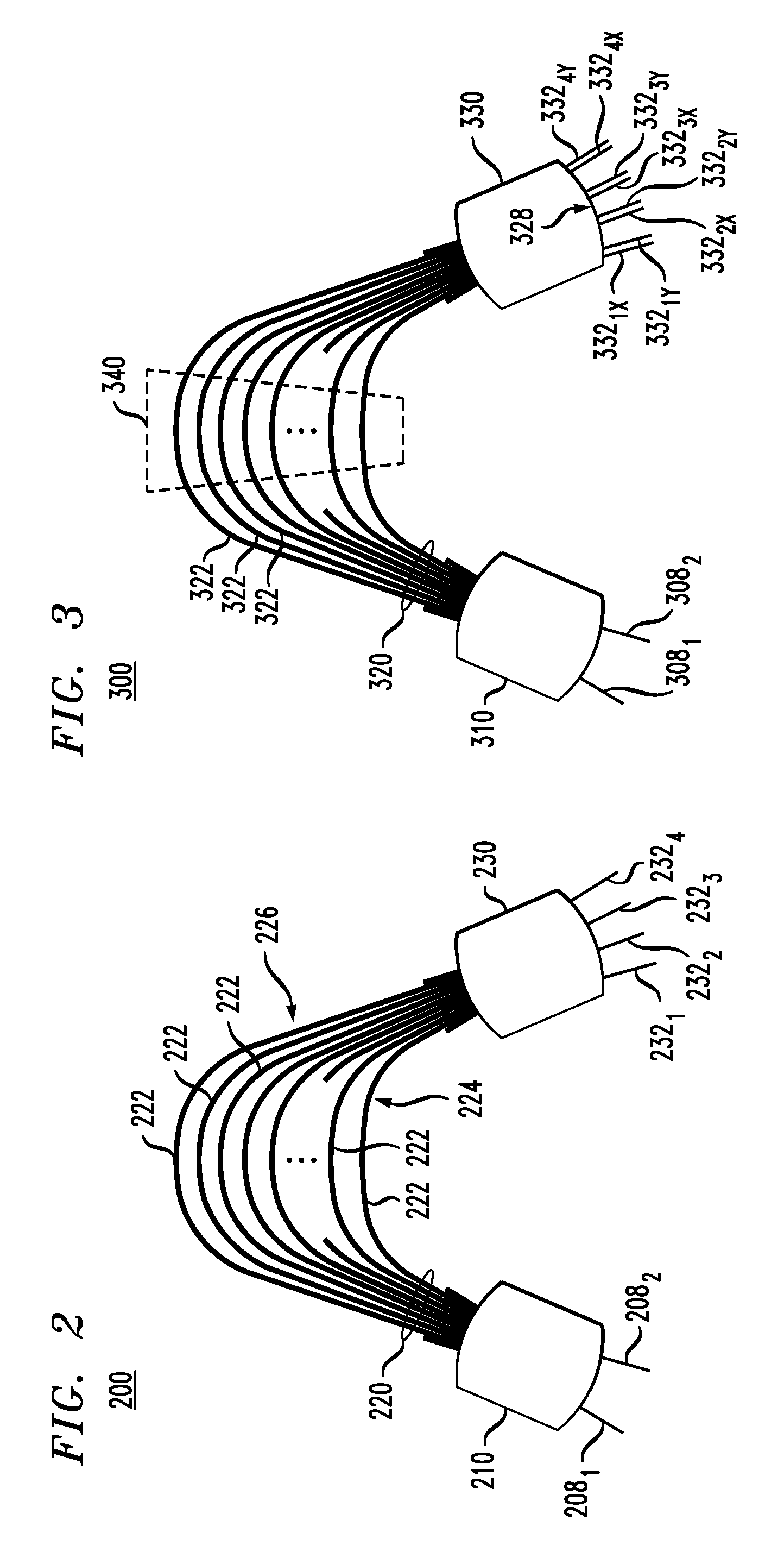
[0038]One advantage of various embodiments of the invention is that the 90-degree-phase characteristic of the hybrid can be highly accurate even when the device is implemented using the photonic-integrated-circuit (PIC) technology. For comparison, in prior-art 90-degree hybrids implemented using the PIC technology, the phase differences for the various outputs of the 90-degree hybrid can significantly deviate from 90 degrees because they are typically determined by a single element, e.g., a multi-mode-interference coupler, used in the hybrid. Thus, even a relatively small error or inaccuracy (e.g., in the dimensions during the fabrication process) of that single element can lead to a significant deviation of the phase differences from the requisite 90 degrees. In contrast, in various embodiments of the present invention, a small error in the length of one particular AWG arm does not have a profound effect on the phase because that error is mitigated by the effective averaging over many AWG arms.

Problems solved by technology

However, one problem with a prior-art optical coherent detector is that it typically requires a separate 90-degree hybrid for each WDM and / or PDM component of the optical communication signal.
Disadvantageously, this multiplicity of constituent devices makes the use of optical coherent detection in WDM and / or PDM systems relatively expensive and causes the corresponding receivers to be relatively large and / or to exhibit relatively high optical attenuation.

Method used


Image

  • Coherent receiver having an interleave-chirped arrayed waveguide grating
  • Coherent receiver having an interleave-chirped arrayed waveguide grating
  • Coherent receiver having an interleave-chirped arrayed waveguide grating

Examples


Embodiment Construction

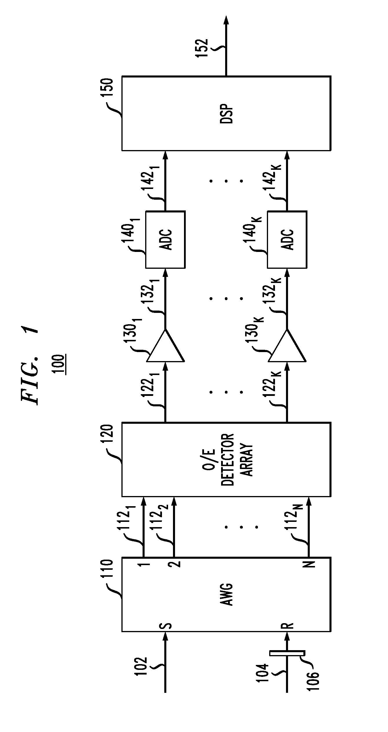
[0016]FIG. 1 shows a block-diagram of a coherent optical receiver 100 according to one embodiment of the invention. Receiver 100 has an arrayed waveguide grating (AWG) 110 having (i) two input ports labeled S and R and (ii) a plurality of output ports labeled 1 through N. AWG 110 optically mixes input signals 102 and 104 applied to input ports S and R, respectively, to generate N mixed signals 1121-112N at output ports 1 through N, respectively. In various embodiments, input signal 102 can be a non-multiplexed signal or a multiplexed signal that has wavelength-division-multiplexed (WDM) and / or polarization-division multiplexed (PDM) signal components. Depending on the intended type of input signal 102, AWG 110 can be designed to perform the functions of: (i) a 90-degree hybrid; (ii) a wavelength demultiplexer and a 90-degree hybrid for each WDM component; (iii) a polarization demultiplexer and a 90-degree hybrid for each PDM component; or (iv) a wavelength demultiplexer, a polarizat...


PUM


Abstract

An optical coherent detector that employs an interleave-chirped arrayed waveguide grating (AWG). The AWG has a periodic chirp pattern that enables the AWG to function as an optical 90-degree hybrid. If the AWG is implemented using a birefringent material, then the AWG can also function as a polarization demultiplexer. In one embodiment, the AWG is designed to simultaneously function as a wavelength demultiplexer, a polarization demultiplexer for each wavelength-division-multiplexed (WDM) signal component, and a 90-degree hybrid for each polarization-division-multiplexed component of each WDM signal component.

Description

BACKGROUND[0001]1. Field of the Invention[0002]The present invention relates to optical communication equipment and, more specifically but not exclusively, to coherent optical receivers.[0003]2. Description of the Related Art[0004]This section introduces aspects that may help facilitate a better understanding of the invention(s). Accordingly, the statements of this section are to be read in this light and are not to be understood as admissions about what is in the prior art or what is not in the prior art.[0005]An optical coherent-detection scheme is capable of detecting not only the amplitude of an optical signal, but also the signal's phase. These capabilities make optical coherent detection compatible with the use of spectrally efficient modulation formats, such as quadrature-amplitude modulation and phase-shift keying (PSK) in its various forms (e.g., differential binary PSK and differential quadrature PSK). Compared to non-coherent detectors, optical coherent detectors offer re...

Claims


Application Information

Patent Timeline
IPC IPC(8): H04J14/06G02B6/26G02B6/34H04B10/06
CPCG02B6/12014G02B6/126H04B10/60H04J14/06H04B10/677H04J14/02H04B10/611H04B10/65H04B10/61H04B10/67
Inventor DOERR, CHRISTOPHER R.
Owner ALCATEL LUCENT SAS
Learn More