Application of Dense Vertically Cracked and Porous Thermal Barrier Coating to a Gas Turbine Component

a gas turbine and thermal barrier coating technology, applied in the direction of superimposed coating process, vessel construction, marine propulsion, etc., can solve the problems of insufficient or possible cooling alone, extreme operating temperature of blades and vanes, stress, strain, etc., and achieve the effect of increasing strain tolerance and temperature capability

Inactive Publication Date: 2011-02-17
ANSALDO ENERGIA IP UK LTD
View PDF15 Cites 39 Cited by
  • Summary
  • Abstract
  • Description
  • Claims
  • Application Information

AI Technical Summary

Benefits of technology

[0004]In accordance with the present invention, there is provided a novel method and configuration for coating a turbine component such as a blade or vane with various forms of thermal barrier coating which provide enhanced temperature capability and increased strain tolerance.

Problems solved by technology

These blades and vanes are subject to extremely high operating temperatures, stresses, and strains.
However, cooling alone is not always sufficient or possible depending on the geometry of the blade or vane and the operating conditions of the engine.

Method used


Image

  • Application of Dense Vertically Cracked and Porous Thermal Barrier Coating to a Gas Turbine Component
  • Application of Dense Vertically Cracked and Porous Thermal Barrier Coating to a Gas Turbine Component
  • Application of Dense Vertically Cracked and Porous Thermal Barrier Coating to a Gas Turbine Component

Examples


Embodiment Construction

[0019]The subject matter of the present invention is described with specificity herein to meet statutory requirements. However, the description itself is not intended to limit the scope of this patent. Rather, the inventors have contemplated that the claimed subject matter might also be embodied in other ways, to include different components, combinations of components, steps, or combinations of steps similar to the ones described in this document, in conjunction with other present or future technologies.

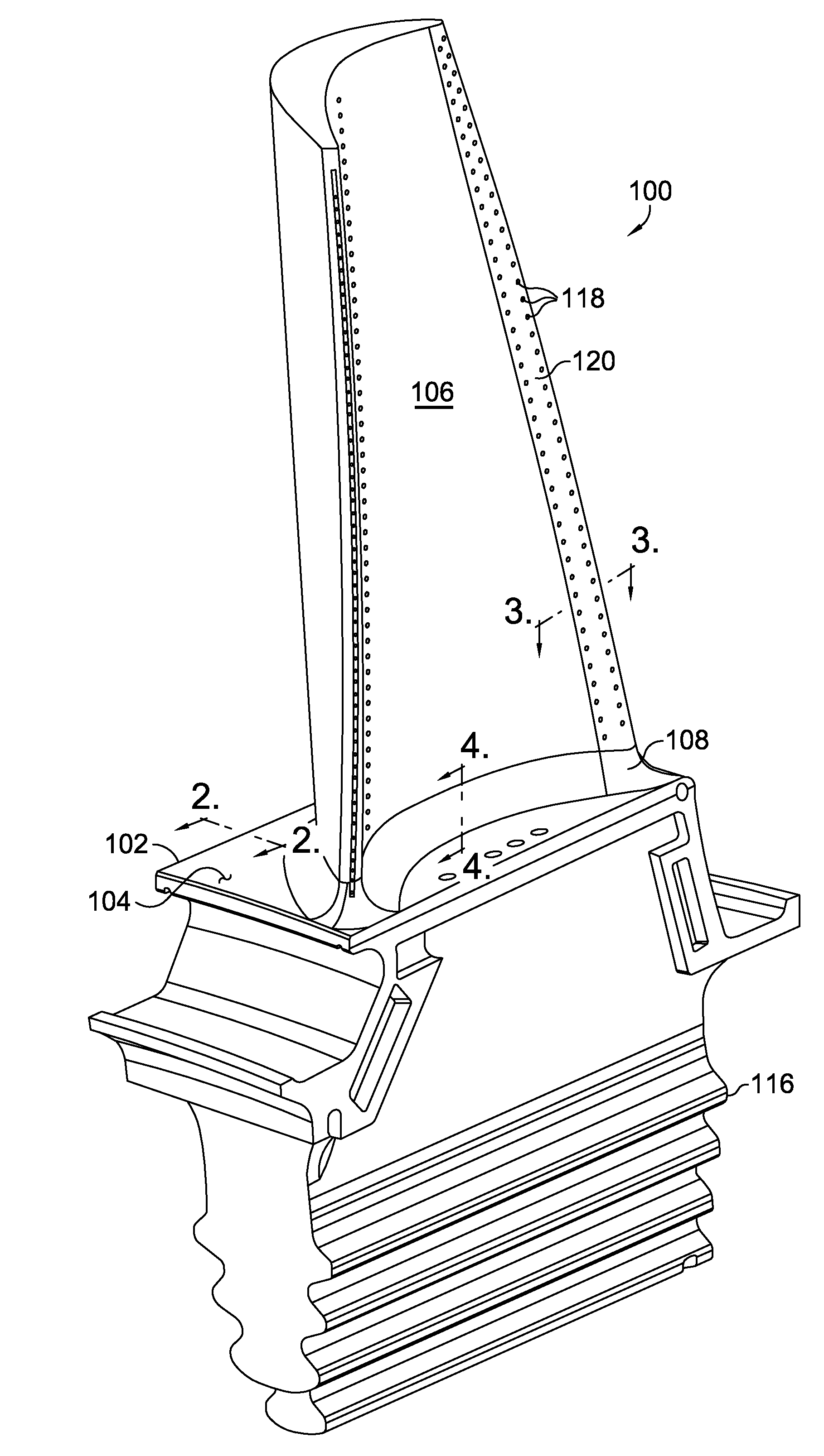
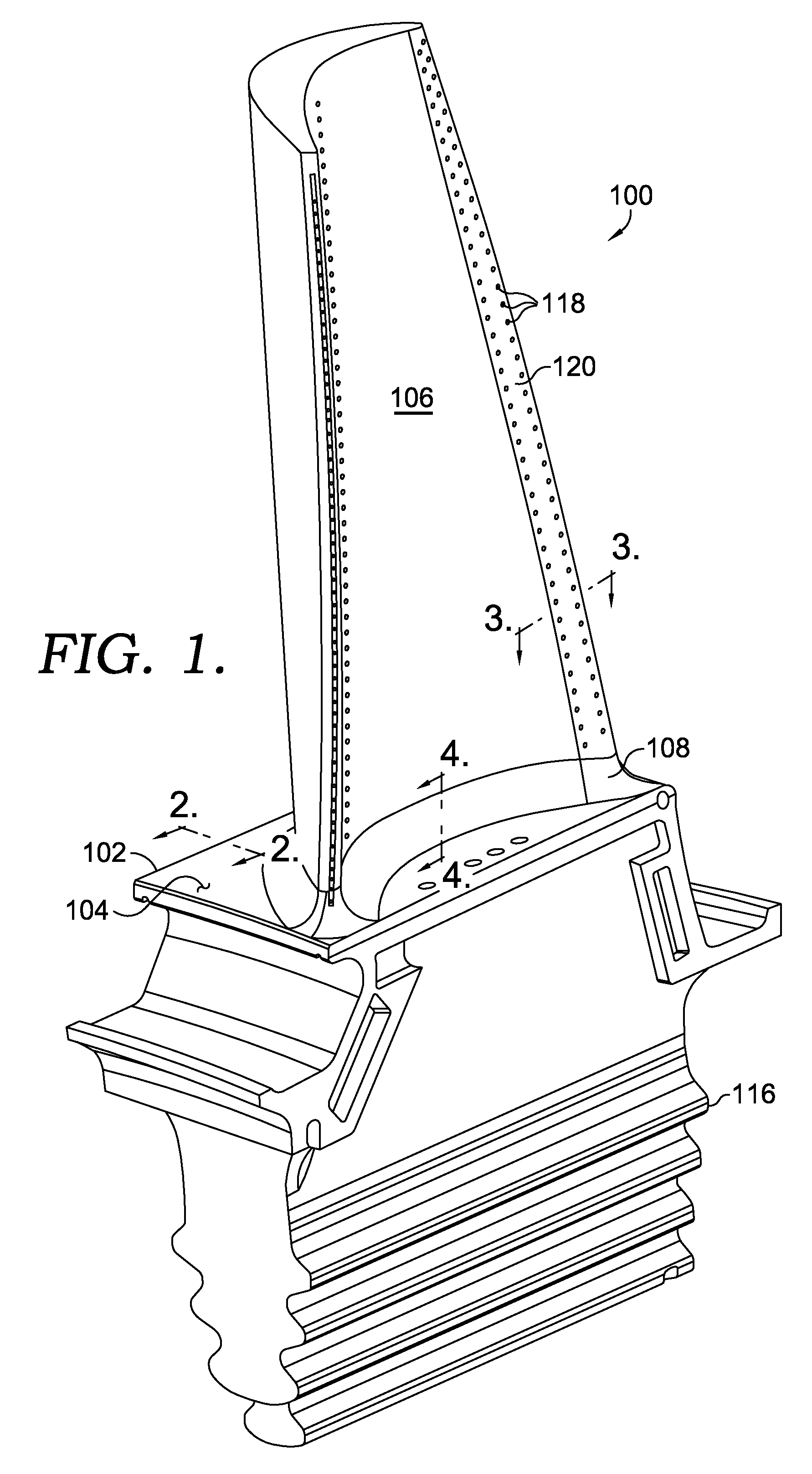
[0020]Referring initially to FIG. 1, a gas turbine blade 100 is shown in perspective view and includes a platform portion 102 having a generally planar gas path surface 104 and an airfoil 106 extending radially outward from the platform 102. Extending around a perimeter of the airfoil 106 at an interface between the airfoil 106 and the platform 102 is a fillet region 108, which is also referred to as a transition zone. The fillet region 108 provides a smooth transition between the a...


PUM

PropertyMeasurementUnit
porosityaaaaaaaaaa
areaaaaaaaaaaa
perimeteraaaaaaaaaa

Abstract

A configuration for coating a turbine component such as a blade or vane with various forms of thermal barrier coating to provide enhanced temperature capability and increased strain tolerance is disclosed. A gas path surface of the platform, airfoil and airfoil fillet region are first coated with a bond coating. A dense vertically cracked (DVC) thermal barrier coating is then applied to at least the gas path surface of the platform and can be applied to the fillet region. A porous thermal barrier coating is then applied to at least the airfoil. The porous thermal barrier coating can also be applied over the DVC thermal barrier coating if desired.

Description

TECHNICAL FIELD[0001]The present invention generally relates to thermal barrier coatings that are applied to gas turbine components. More specifically, the present invention relates to using different forms of a thermal barrier coating for application on a gas turbine blade or vane.BACKGROUND OF THE INVENTION[0002]Gas turbine engines operate to produce mechanical work or thrust. Specifically, land-based gas turbine engines typically have a generator coupled thereto for the purposes of generating electricity. A gas turbine engine comprises an inlet that directs air to a compressor section, which has stages of rotating compressor blades. As the air passes through the compressor, the pressure of the air increases. The compressed air is then directed into one or more combustors where fuel is injected into the compressed air and the mixture is ignited. The hot combustion gases are then directed from the combustion section to a turbine section by a transition duct. The hot combustion gase...

Claims


Application Information

Patent Timeline
Patent Type & Authority Applications(United States)
IPC IPC(8): F01D25/08B05D1/36F01D5/18
CPCC23C4/06C23C4/124C23C4/127F05D2230/80F01D5/288F05D2230/90C23C28/00C23C4/01C23C4/02C23C4/11C23C4/129C23C4/134C23C28/3215C23C28/3455
Inventor KEMPPAINEN, DANARAWLINGS, RUTHANNKLEMM-TOOLE, JONAHMOORE, ROBERT
Owner ANSALDO ENERGIA IP UK LTD
Why Eureka
Try Eureka