
Kiln tool plate for firing ceramic material

a technology of kiln tool plate and ceramic material, which is applied in the direction of charging supports, lighting and heating apparatus, furnaces, etc., can solve the problems of large ratio of kiln tool weight to product weight, easy discharge of binding gas, and large amount of kiln tool weight, so as to reduce the weight of kiln tool and reduce the cost , the effect of improving the outgassing

Active Publication Date: 2011-02-17
NGK INSULATORS LTD
View PDF14 Cites 11 Cited by
  • Summary
  • Abstract
  • Description
  • Claims
  • Application Information

AI Technical Summary

Benefits of technology

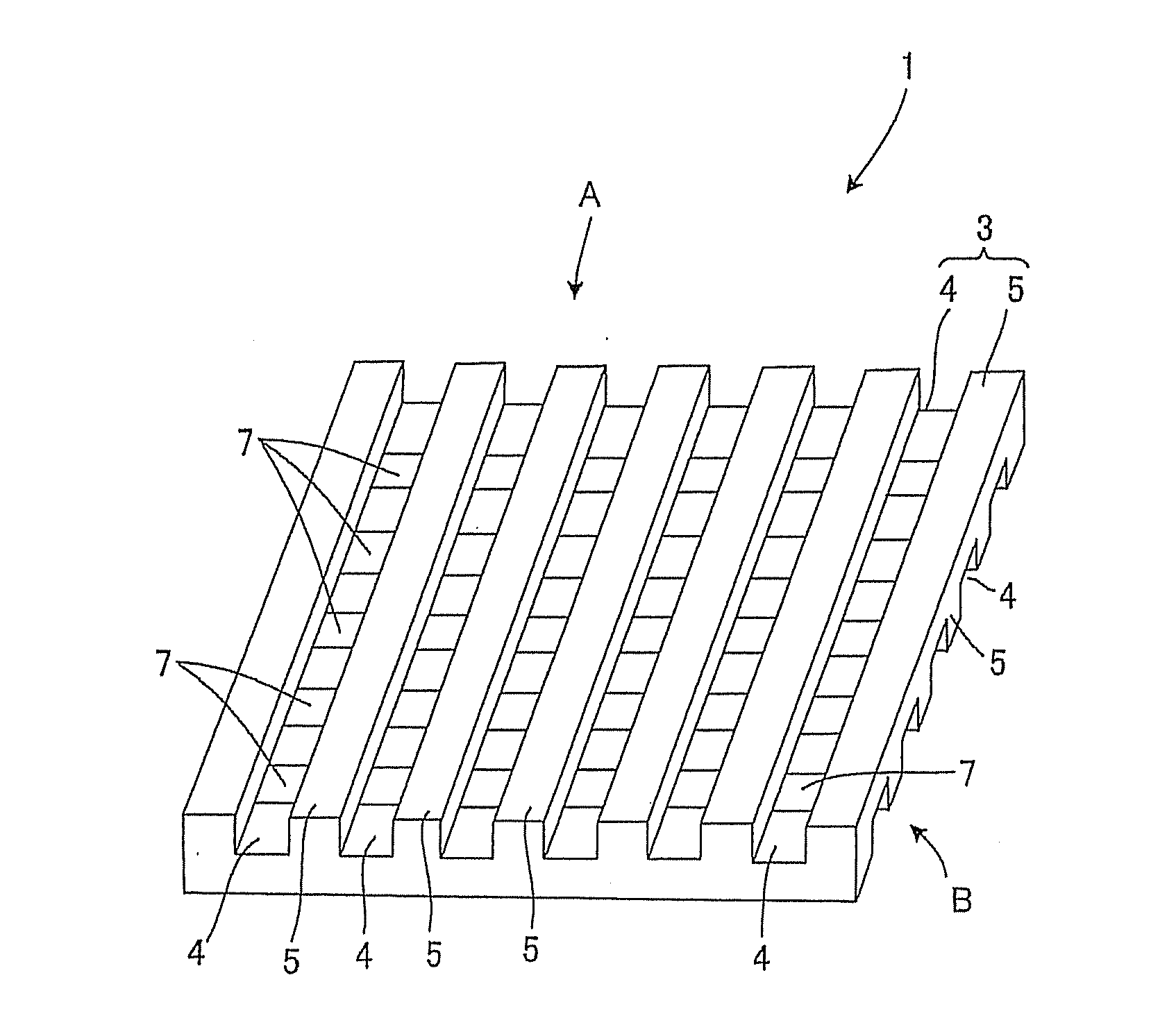
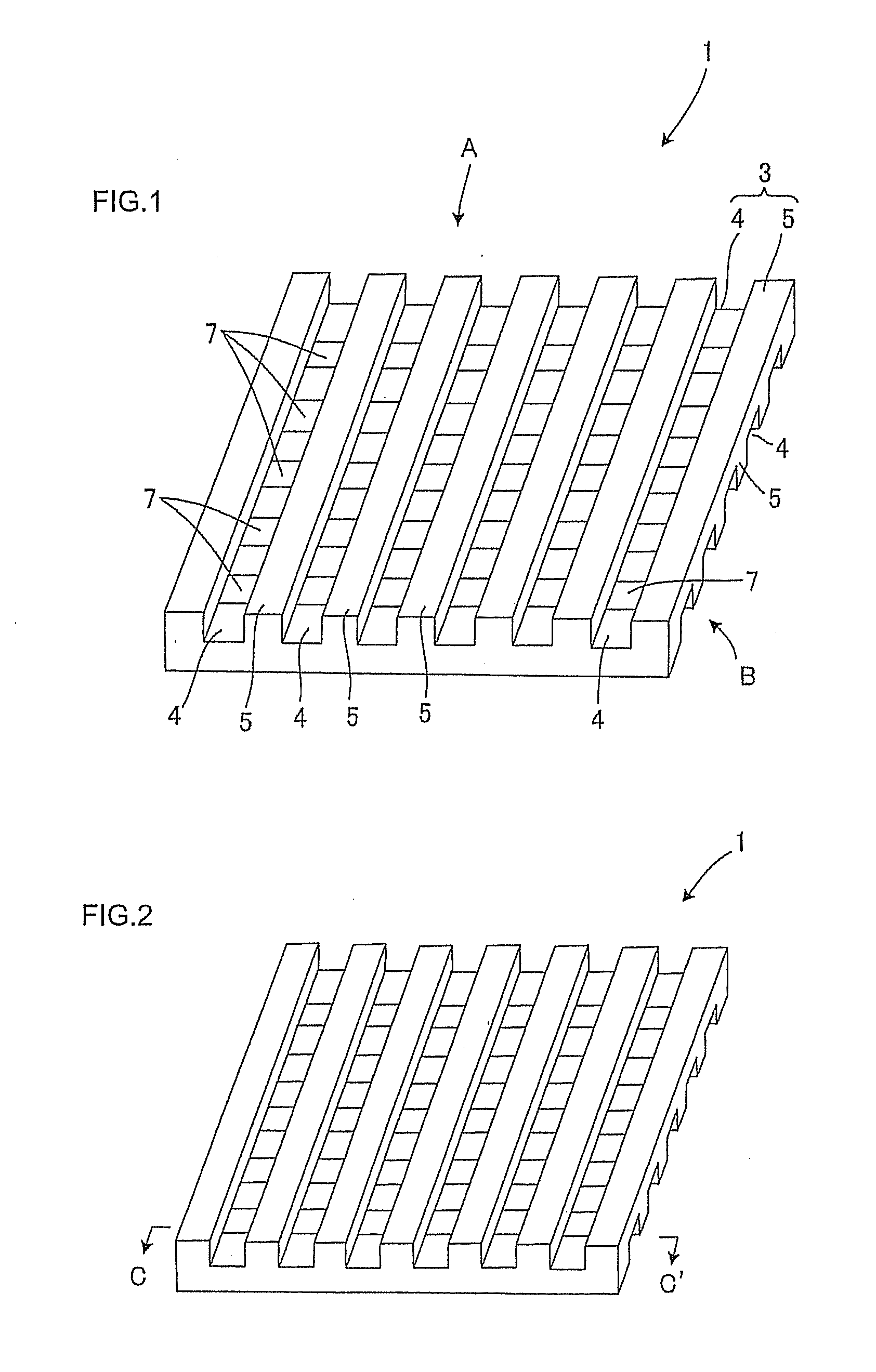
[0013]The present invention has been developed to solve the above problems, and an object thereof is to provide a kiln tool plate for firing a ceramic material in which at least uneven conformations are imparted to a front surface side with an article to be fired mounted thereon and a back surface side and in which opening areas are formed, whereby heat capacity decrease and cost reduction can be achieved. There is provided a kiln tool plate for firing a ceramic material in which a contact area with an article to be fired is decreased to improve outgassing and in which the atmosphere can be made uniform to uniformly manufacture the fired article. Above all, there is provided a kiln tool plate for firing a ceramic material having excellent thermal shock resistance, creep resistance, high strength at high temperature and oxidation resistance while enabling weight saving.
[0026]The present invention produces an excellent effect that there can be provided the kiln tool plate for firing the ceramic material in which heat capacity decrease and cost reduction can be achieved, the contact area with the article to be fired is decreased to improve outgassing, and the atmosphere can be made uniform to uniformly manufacture the fired article. Above all, there can be provided the kiln tool plate for firing the ceramic material having excellent thermal shock resistance, creep resistance, high strength at high temperature and oxidation resistance.

Problems solved by technology

However, when the article to be fired is mounted and fired on the ceramic material firing kiln tool plate having the plate shape, a binder gas included in the article to be fired is not easily discharged, thereby causing a problem that a temperature difference occurs in a product to generate a breakage defect, or another problem that a binder residue during the firing hampers sintering to generate the breakage defect.
Moreover, owing to a large contact area, the binder gas is not easily discharged.
In addition, the contact with an atmospheric gas becomes insufficient during the firing, and hence the atmosphere is confined, with the result that the breakage defect is generated.
The article easily adheres to a setter owing to the contraction during the sintering, which also generates a problem such as a crack or breakage defect.
In Patent Document 1, however, the ratio of the weight of a kiln tool with respect to a product weight is large, and a large loss takes place from the aspect of energy saving.
Moreover, the binder gas is not sufficiently discharged during the firing, so that a temperature difference in the product still easily occurs, and a breakage defect is easily generated.
Moreover, the atmosphere is easily confined, and the contact of the product with the atmospheric gas becomes insufficient during the firing, and the breakage defect is further easily generated.
However, the ratio of the weight of a kiln tool with respect to a product weight is large, a large loss is incurred from the aspect of energy saving, and a binder gas is not sufficiently discharged during firing.
Moreover, owing to a large contact area with a product, the product is easily deformed owing to contraction during sintering, and might adhere to the ceramic base plate.
In addition, the possibility of the occurrence of a fluctuation during manufacturing, for example, a crack or breakage defect, cannot be denied.
However, it cannot be considered that a binder gas is sufficiently discharged during firing.
Moreover, an atmospheric gas is easily confined.
In addition, the ratio of the weight of a kiln tool with respect to a product weight is large, and a large loss is incurred from the aspect of energy saving.
It cannot be considered that a countermeasure is sufficiently taken against deformation or the like due to contraction during sintering.

Method used


Image

  • Kiln tool plate for firing ceramic material
  • Kiln tool plate for firing ceramic material
  • Kiln tool plate for firing ceramic material

Examples


examples

[0124]Hereinafter, the present invention will further specifically be described with respect to examples, but the present invention is not limited to the examples. It is to be noted that hereinafter, ‘%’ in the examples and comparative examples indicates mass %, unless otherwise specified. Moreover, various evaluations and measurements in the examples were performed by methods described hereinafter.

[0125][1-1] Bulk Specific Gravity:

[0126]As to a bulk specific gravity, after drying a material in a drying chamber at 80° C. for 12 hours, a dry mass W1 was measured. Afterward, the material was boiled in water at 100° C. for one hour, and cooled down to ordinary temperature in the water. Subsequently, after measuring an in-water mass W2 and wiping the whole material with lightly squeezed gauze, a water-containing weight W3 was measured. The bulk specific gravity was calculated from these values W1, W2 and W3.

[0127][1-2] Bending Strength:

[0128]A breaking weight was measured by a three-poi...


PUM

PropertyMeasurementUnit
diametersaaaaaaaaaa
pore diametersaaaaaaaaaa
thicknessaaaaaaaaaa

Abstract

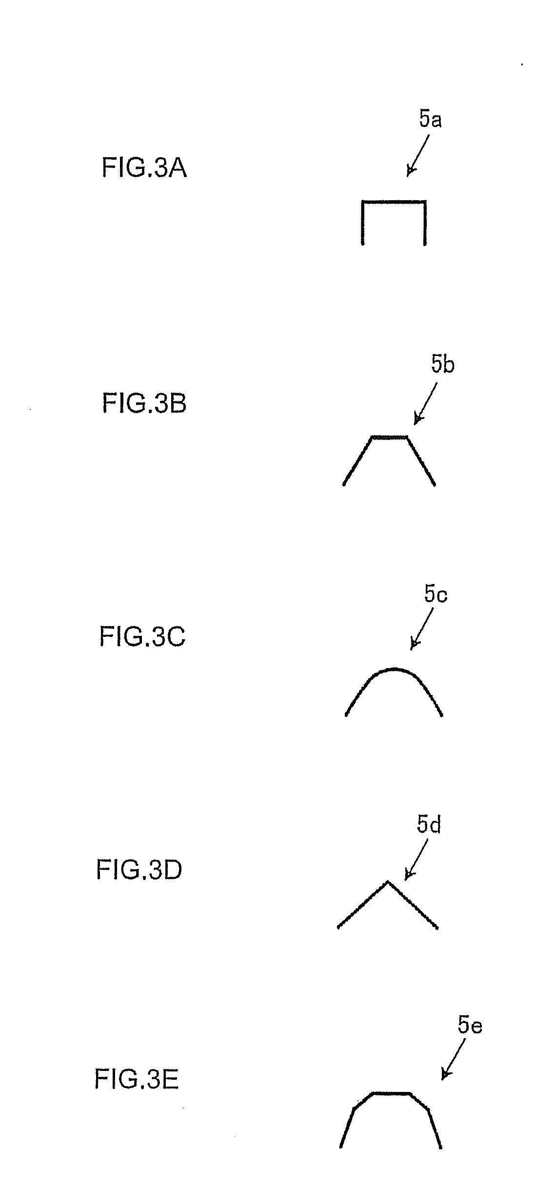
A kiln tool plate 1 for firing a ceramic material used during the firing of an article to be fired, wherein at least uneven conformations 3 are imparted to a front surface side A on which the article to be fired is mounted and a back surface side B, and opening areas 7 are formed. In the ceramic material firing kiln tool plate 1, the decrease of heat capacity and the reduction of costs can be achieved, a contact area with the article to be fired is decreased to improve outgassing, and the atmosphere can be made uniform to uniformly manufacture the fired article. Above all, the kiln tool plate for firing the ceramic material has excellent thermal shock resistance, creep resistance, high strength at high temperature and oxidation resistance, and enables weight saving.

Description

TECHNICAL FIELD[0001]The present invention relates to a lightweight setter. More particularly, it relates to a lightweight setter for a shelf assembly having a beam structure used to fire a formed honeycomb article.BACKGROUND ART[0002]Heretofore, as a ceramic material firing kiln tool plate used during the firing of an article to be fired such as a formed honeycomb article, there has been known a ceramic material firing kiln tool plate which comes in contact with the article to be fired and which has a plate shape.[0003]However, when the article to be fired is mounted and fired on the ceramic material firing kiln tool plate having the plate shape, a binder gas included in the article to be fired is not easily discharged, thereby causing a problem that a temperature difference occurs in a product to generate a breakage defect, or another problem that a binder residue during the firing hampers sintering to generate the breakage defect.[0004]Moreover, owing to a large contact area, the...

Claims


Application Information

Patent Timeline
Patent Type & Authority Applications(United States)
IPC IPC(8): F27D5/00
CPCB28B11/248C04B35/565C04B35/6316C04B35/64C04B2235/3418C04B2235/3873F27D5/0012C04B2235/77C04B2235/80C04B2235/945C04B2235/95C04B2235/96C04B2235/9623C04B2235/428Y02P40/60
Inventor HANZAWA, SHIGERUKOMIYAMA, TSUNEO
Owner NGK INSULATORS LTD
Learn More