Ultrasonic diagnostic apparatus

a diagnostic apparatus and ultrasonic technology, applied in the field of ultrasonic diagnostic apparatus, to achieve the effect of accurate detection of absolute pressure, enhanced usability, and simplified operation

Inactive Publication Date: 2011-02-17
HITACHI LTD
View PDF4 Cites 12 Cited by
  • Summary
  • Abstract
  • Description
  • Claims
  • Application Information

AI Technical Summary

Benefits of technology

[0027]According to the present invention, it is possible to accurately detect the ab

Problems solved by technology

On the other hand, in the bloodstream test such as the Doppler measurement, the CFM, or the like, since it is not possible to obtain correct information on the bloodstream because the cross-section of the blood vessel is deforme

Method used


Image

  • Ultrasonic diagnostic apparatus
  • Ultrasonic diagnostic apparatus
  • Ultrasonic diagnostic apparatus

Examples


Embodiment Construction

[0055]Hereinafter, a description will be made of the embodiments of the ultrasonic diagnostic apparatus according to the present invention with reference to the drawings.

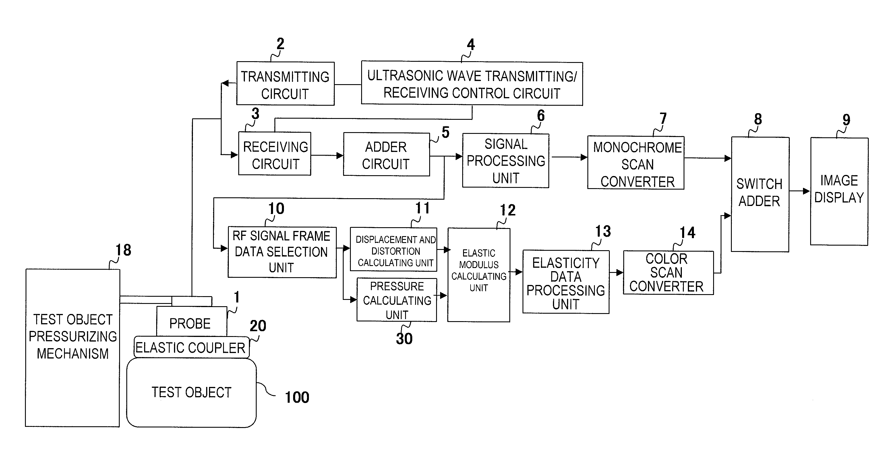
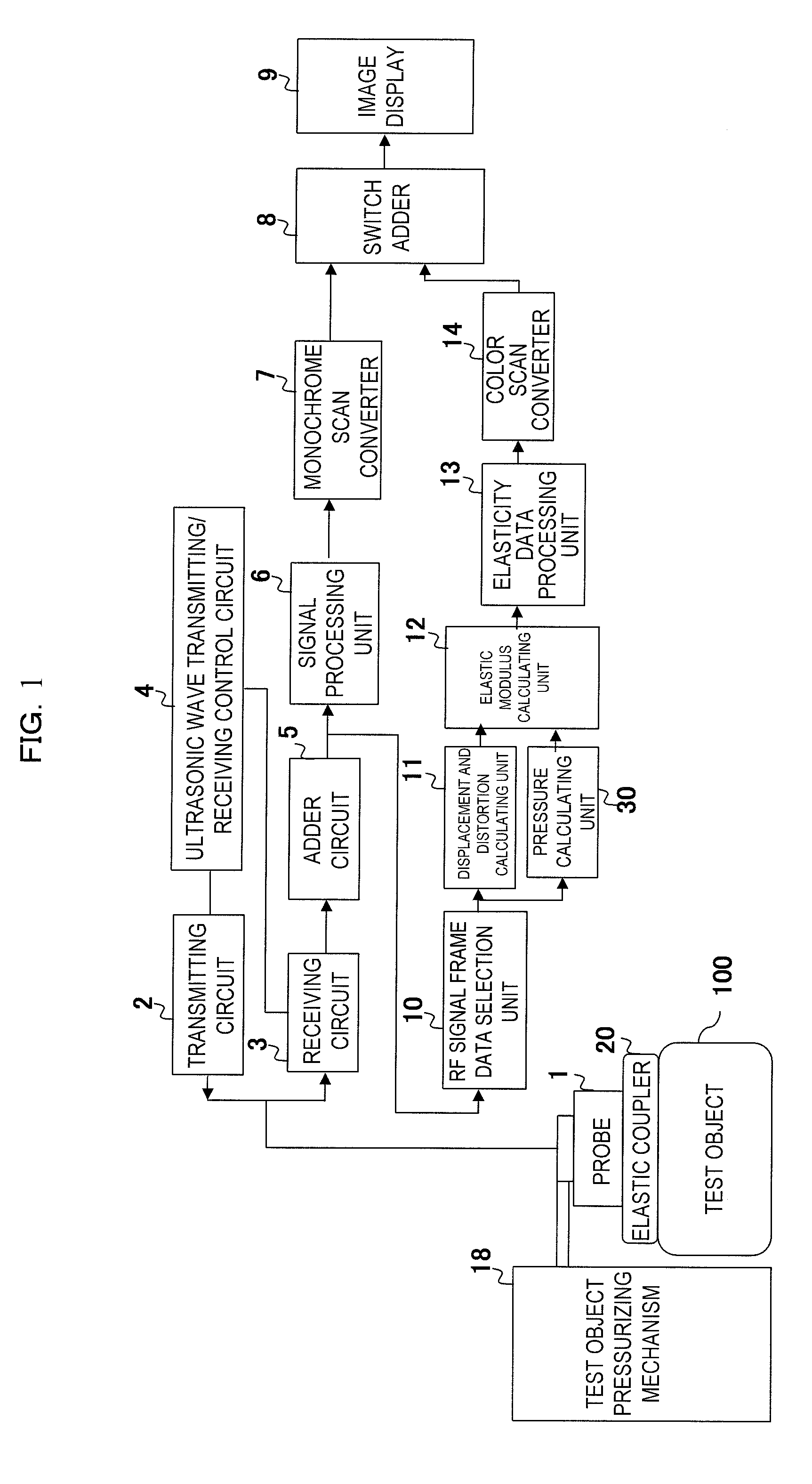
[0056]FIG. 1 shows a functional block configuration diagram of an embodiment in which the present invention is applied to an ultrasonic diagnostic apparatus for performing the test based on elastic information.

[0057]As shown in FIG. 1, the ultrasonic diagnostic apparatus of this embodiment is for obtaining a tomographic image of a site as a diagnostic target of the object with the use of ultrasonic waves and obtaining an elasticity image representing the hardness or the softness of the body tissue. As shown in the same drawing, an ultrasonic probe (hereinafter, simply referred to as a probe) 1 is electrically connected to a transmitting circuit 2 and a receiving circuit 3. As is well known, the probe 1 is a generation source of the ultrasonic waves and is formed such that a plurality of oscillators for receiving the...


PUM


Abstract

The present invention is made to accurately detect an absolute pressure even when a contact property between an elastic coupler and a body surface of an object is poor. An elastic coupler 20 is formed by an elastic material with flexibility to have two layers at least with different ultrasonic wave reflectance properties and attached to an ultrasonic wave transmitter/receiver surface, and a pressure calculating unit 30 detects the position of a boundary surface 22 between those two layers based on RF signal frame data output from an RF signal frame data selection unit 10, obtains positional change of the boundary surface based on the detected position of the boundary surface and the initial position of the boundary surface, which was obtained in advance, and obtains the absolute pressure applied to the object based on the positional change and a pre-set elasticity property of the elastic coupler. At this time, for example, an ID code is given to the elastic coupler by making the initial position or the like of the boundary surface of the elastic coupler be different in accordance with the type of the elastic coupler, the pressure calculating unit 30 identifies the ID code, identifies the type of the elastic coupler with reference to a coupler database, and reads the elasticity property corresponding to the ID code.

Description

TECHNICAL FIELD[0001]The present invention relates to an ultrasonic diagnostic apparatus, and particularly to a technique for making it possible to detect an absolute pressure to be applied to an object to be examined by an ultrasonic probe at the time of a test such as a diagnosis by a tomographic image (B mode image) or elastic information of a body tissue of an object, or a bloodstream diagnosis by Doppler measurement or a color flow mode (CFM).BACKGROUND ART[0002]Generally, an ultrasonic diagnostic apparatus is for performing a diagnosis such that ultrasonic waves are transmitted into a body of an object from an ultrasonic probe (hereinafter, simply referred to as a probe), a reflected echo signal of the ultrasonic waves which have been reflected from the inside of the body is received by the probe, and an image or the like which is suitable for the test of a tissue, a function, or the like inside the body is created based on the received reflected echo signal (RF signal).[0003]...

Claims


Application Information

Patent Timeline
IPC IPC(8): A61B8/14
CPCA61B5/6843A61B8/06A61B8/488A61B8/13A61B8/4455A61B8/08
Inventor MATSUMURA, TAKESHI
Owner HITACHI LTD
Why Eureka
Try Eureka