Method for power overload control in a network

Inactive Publication Date: 2011-02-17
MOXA INC
View PDF2 Cites 13 Cited by
  • Summary
  • Abstract
  • Description
  • Claims
  • Application Information

AI Technical Summary

Benefits of technology

[0011]The primary object of the present invention is to utilize an Ethernet switching device that is capable of controlling total power consumption of network powered devices to ensure that the total power consumption does not exceed the total power supplied by an external power source to the network powered devices, thus preventing shut-off of power supply to the whole operating system in an enterprise and further preventing halting of production. This method employs a PoE control unit in the Ethernet switching device to detect network powered devices regularly. When detecting any power overload on network powered devices, the PoE control unit will send signals to a central processing unit (CPU), which decides which of the network powered devices needs to be switched off based on the preset conditions for power supply, follo

Problems solved by technology

As a result, use of these network devices is subject to the position of power supply, and these devices will become useless in the places where power supply is not available.
If user managers “plan” or “operate” the system power of Ethernet switching devices improperly, it may cause total power consumption of the Ethernet switching devices and network powered devices they connect to be larger than the total load power supplied by external power supplies, thus further causing power protection mechanisms to be started, and the power supply to the whole system will be cut off.
But this approach often causes the system to halt for a long period, and in industrial environments involving production operations, it will delay the production time and cause heavy losses to enterprises' assets.
On the other hand, if the power supply to the system is halted suddenly, it may cause working system equipments to fa

Method used


Image

  • Method for power overload control in a network
  • Method for power overload control in a network
  • Method for power overload control in a network

Examples


Embodiment Construction

[0019]To achieve the aforesaid objects and functions as well as the techniques applied in the present invention and its fabrication, an example of the preferred embodiment of the present invention is given to describe the features and functions of the present invention in detail by referring to the accompanying drawings.

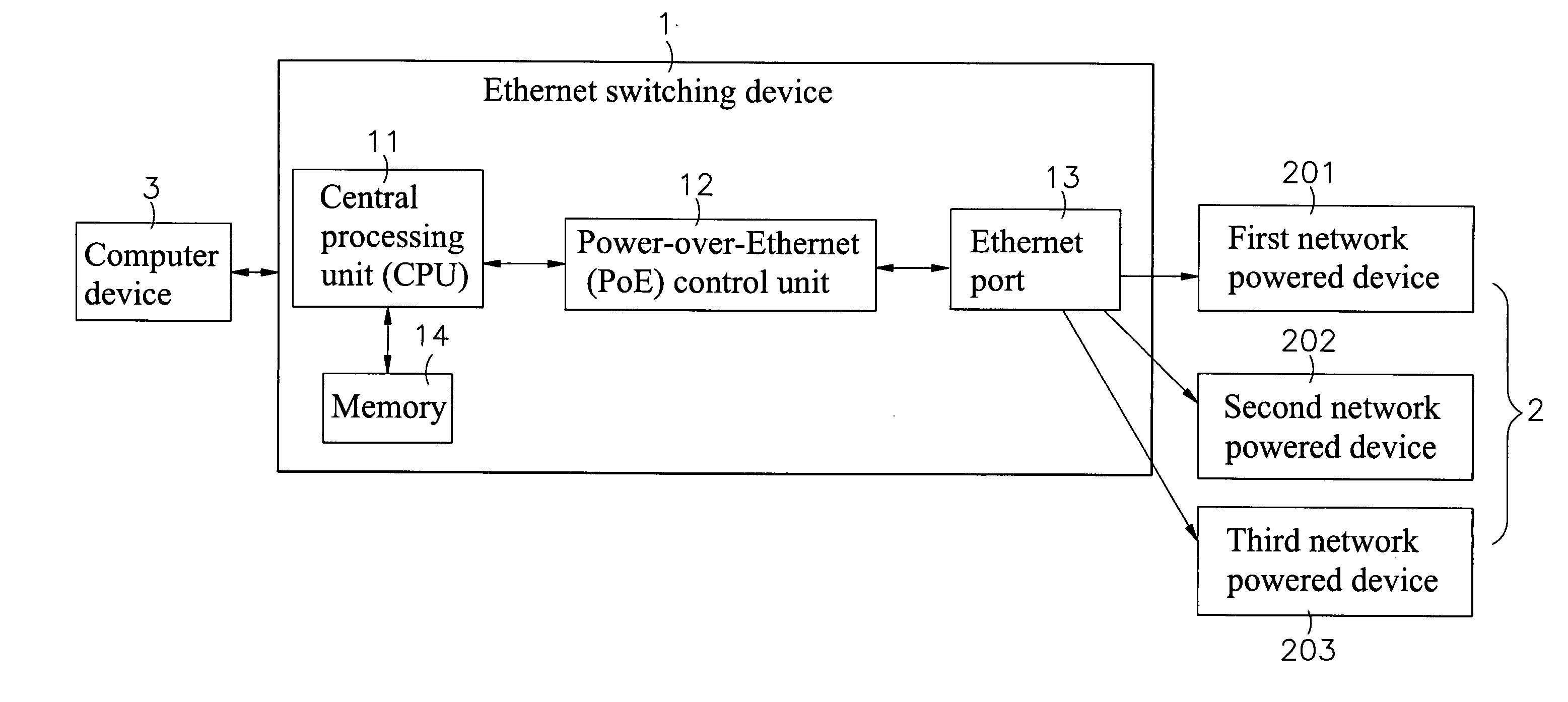
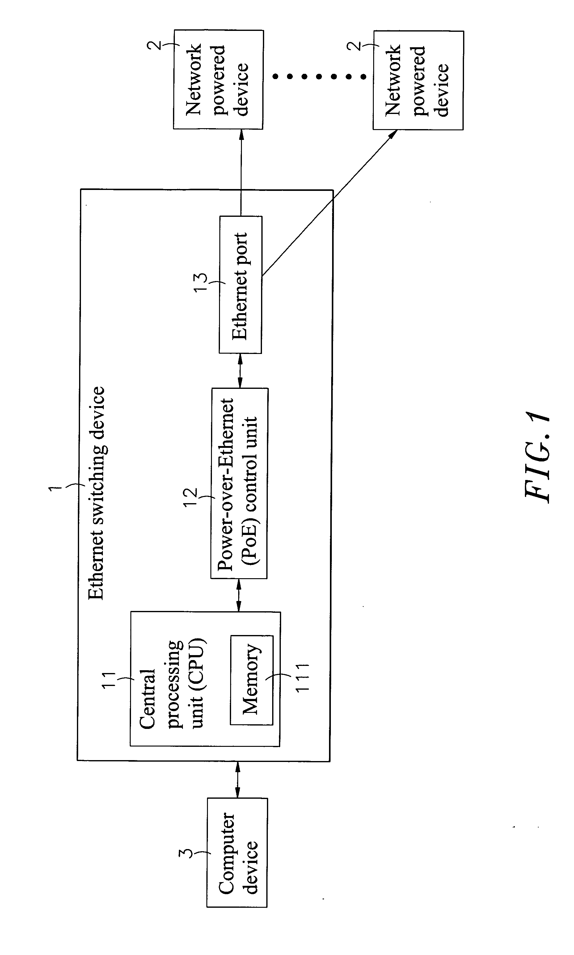
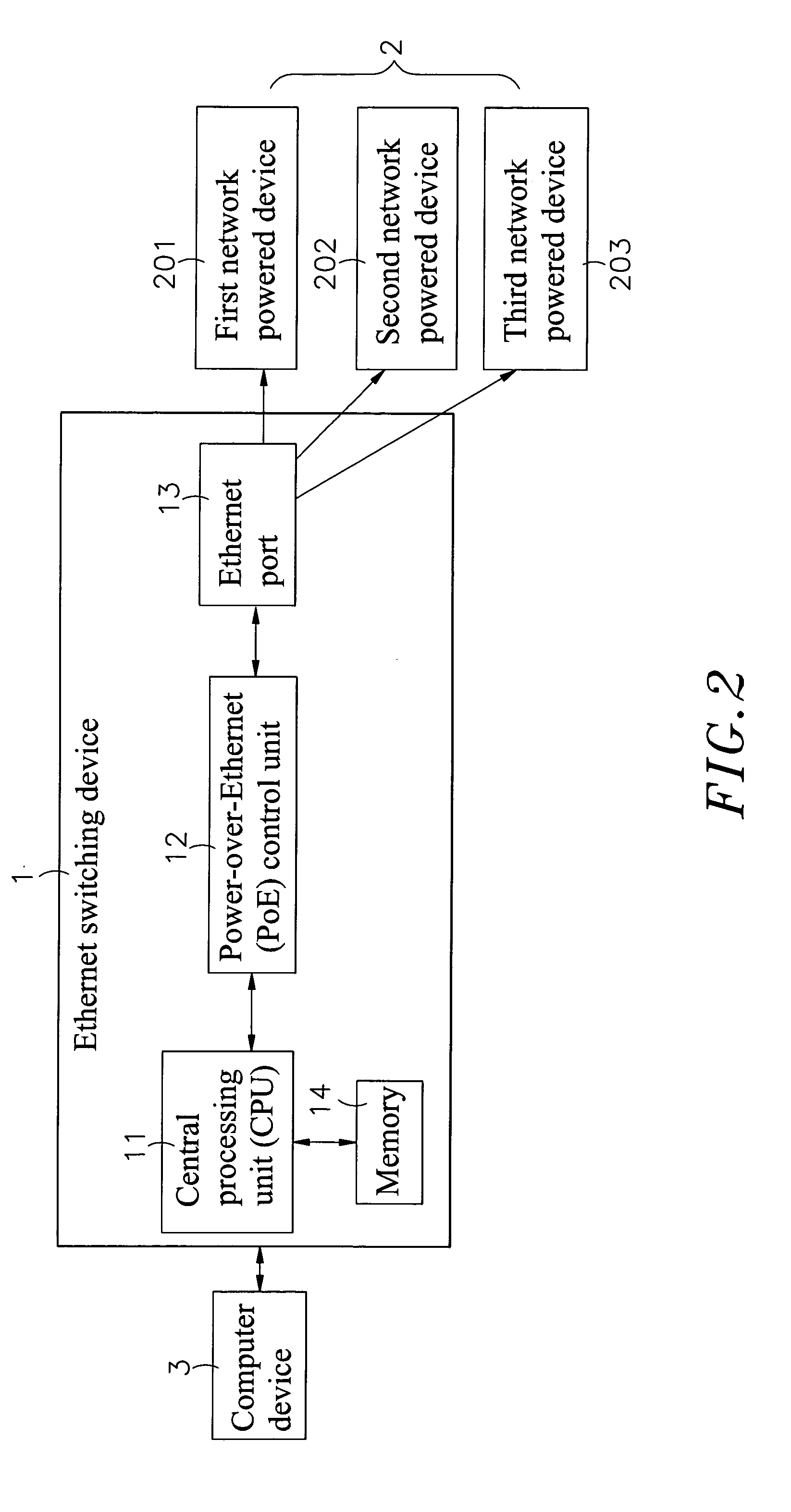
[0020]Refer to FIG. 1, which clearly shows that the present invention comprises an Ethernet switching device 1, a network powered device 2 and a computer device 3, wherein:

[0021]The Ethernet switching device 1 includes a central processing unit (CPU) 11, which has a memory 111 inside and is connected with a Power-over-Ethernet (PoE) control unit 12 that is further linked with an Ethernet port 13. The Ethernet port 13 may be an RJ45 or a component for Ethernet connection in any other form, and one or more Ethernet ports 13 can be equipped. The CPU 11, the PoE control unit 12 and the Ethernet port 13 are installed in a proposed electronic circuit module of the Ethernet...


PUM


Abstract

The present invention relates to a method for power overload control in a network, comprising an Ethernet switching device and a plurality of network powered devices, wherein the Ethernet switching device includes a central processing unit (CPU), a Power-over-Ethernet (PoE) control unit and an Ethernet port. The PoE control unit can regularly check if any of the plurality of network powered devices is overloaded, and in case of any overload, will transmit signals to the CPU, which will further decide on the network powered devices to be selected for disconnection according to the preset conditions for supplying power to avoid interferences over major network powered devices and reduce losses to enterprises effectively. Besides, when the network powered device is disconnected, the CPU will again send warning signals to the computer device, so that managers can be informed of the status of the remote terminals and then reschedule the power supply immediately and eliminate failures quickly.

Description

BACKGROUND OF THE INVENTION[0001]1. Field of the Invention[0002]The present invention relates to a method for power overload control in a network, in which an Ethernet switching device is used to cut off the power supply to a specific network powered device (PD) in the network to reduce the cases where the major network PD fails in the network and reduce the losses to enterprises in property.[0003]2. Description of the Prior Art[0004]With rapid progress in computer technology, computer devices become widespread in every corner of the society, while quick developments in network technology also open a new chapter in peoples' life, learning, study and entertainment. Under such circumstances, people can contact and communicate with each other by delivering messages among them via a network. Currently, communication of computers with networks is enabled mainly by using components for Ethernet, such as RJ45. However, such network equipments connected with wired Ethernet networks shall us...

Claims


Application Information

Patent Timeline
IPC IPC(8): G06F1/00
CPCH04L69/40G06F1/266Y02B60/1282G06F1/3287H04L12/40045G06F1/3209Y02D10/00
Inventor WU, PO-SHENG
Owner MOXA INC
Why Eureka
Try Eureka