System and method of dual laser beam welding of first and second filler metals

a laser beam welding and filler metal technology, applied in the field of laser beam welding, can solve the problems of poor fatigue strength, catastrophic failure of the weld joint, and relatively difficult process of welding together of superalloy materials

Inactive Publication Date: 2011-02-24
GENERAL ELECTRIC CO
View PDF24 Cites 47 Cited by
  • Summary
  • Abstract
  • Description
  • Claims
  • Application Information

AI Technical Summary

Benefits of technology

[0010]Another exemplary embodiment of the present invention concerns a system for laser beam welding at least two superalloy components including a first filler metal, a second filler metal, an energy source and a controller. The first filler metal is provided within a joint formed between at least first and second superalloy components. The second filler metal is fed over the joint formed between the at least first and second superalloy components. The energy source provides first and second laser beams at respective first and s

Problems solved by technology

The welding together of superalloy materials has been a relatively difficult process requiring very particular welding conditions.
One drawback to these beam processes is the directional grain growth in the fusion zone which forms a distinct dendritic boundary in the center of the weld zone.
This type of grain structure makes the joint vulnerable to centerline cracking and results in very poor fatigue strength, which can result in catastrophic failure of the weld joint during operation of a gas turbine.
However, this process is limited by the joint thickness.
Also, lack of pen

Method used


Image

  • System and method of dual laser beam welding of first and second filler metals
  • System and method of dual laser beam welding of first and second filler metals
  • System and method of dual laser beam welding of first and second filler metals

Examples


Embodiment Construction

[0021]Reference now will be made in detail to embodiments of the invention, one or more examples of which are illustrated in the drawings. Each example is provided by way of explanation of the invention, not limitation of the invention. In fact, it will be apparent to those skilled in the art that various modifications and variations can be made in the present invention without departing from the scope or spirit of the invention. For instance, features illustrated or described as part of one embodiment, can be used with another embodiment to yield a still further embodiment. Thus, it is intended that the present invention covers such modifications and variations as come within the scope of the appended claims and their equivalents.

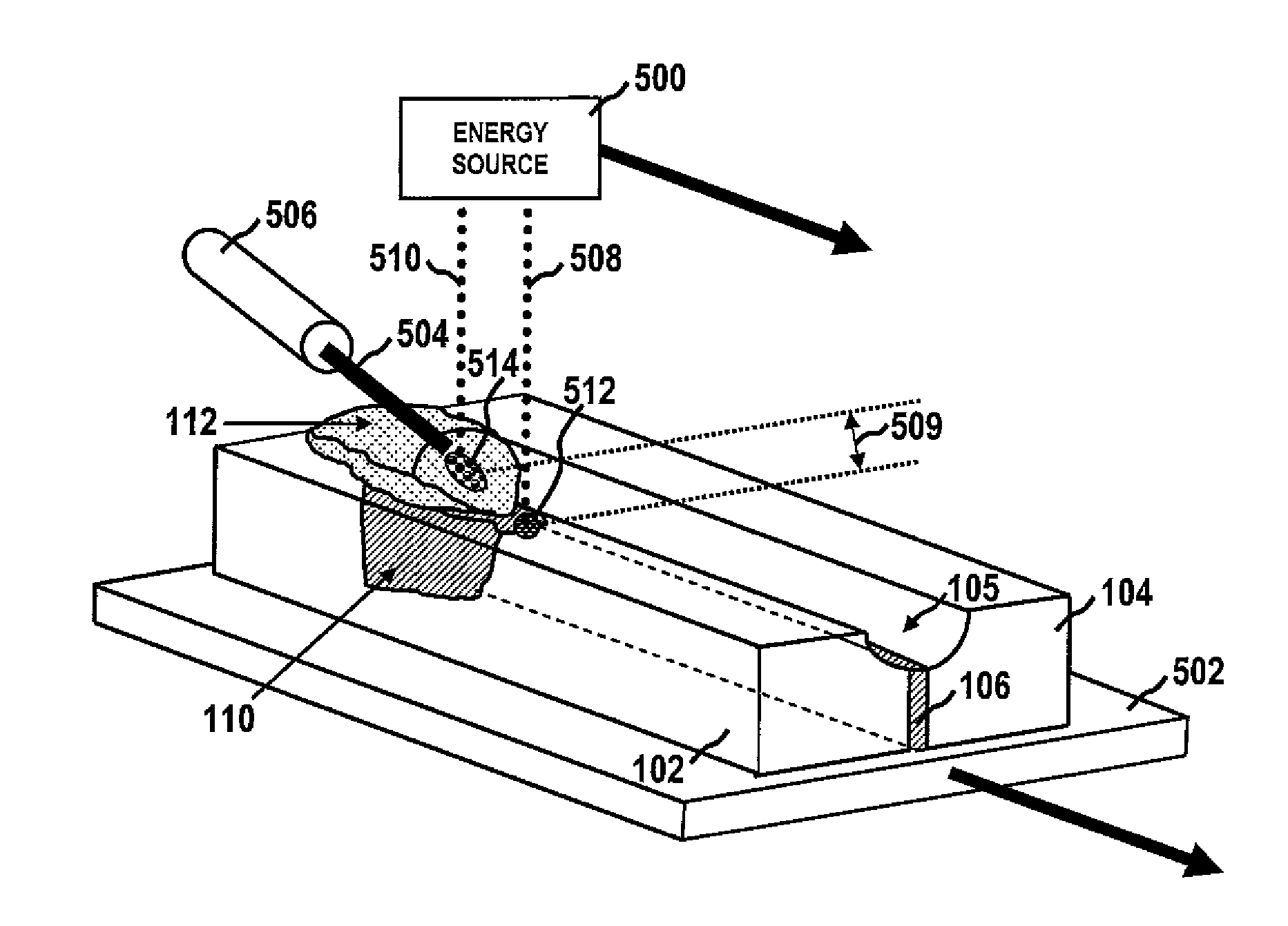
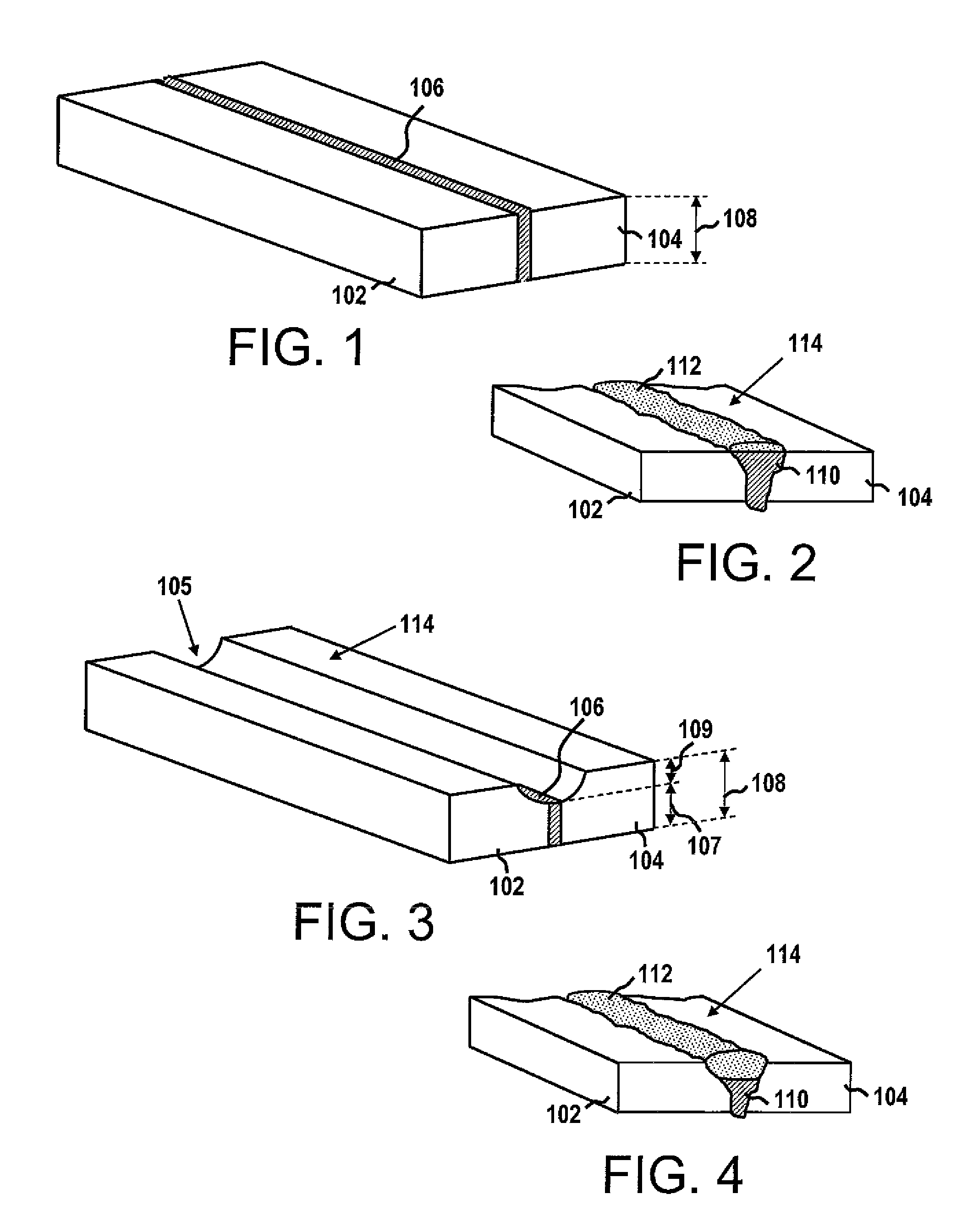
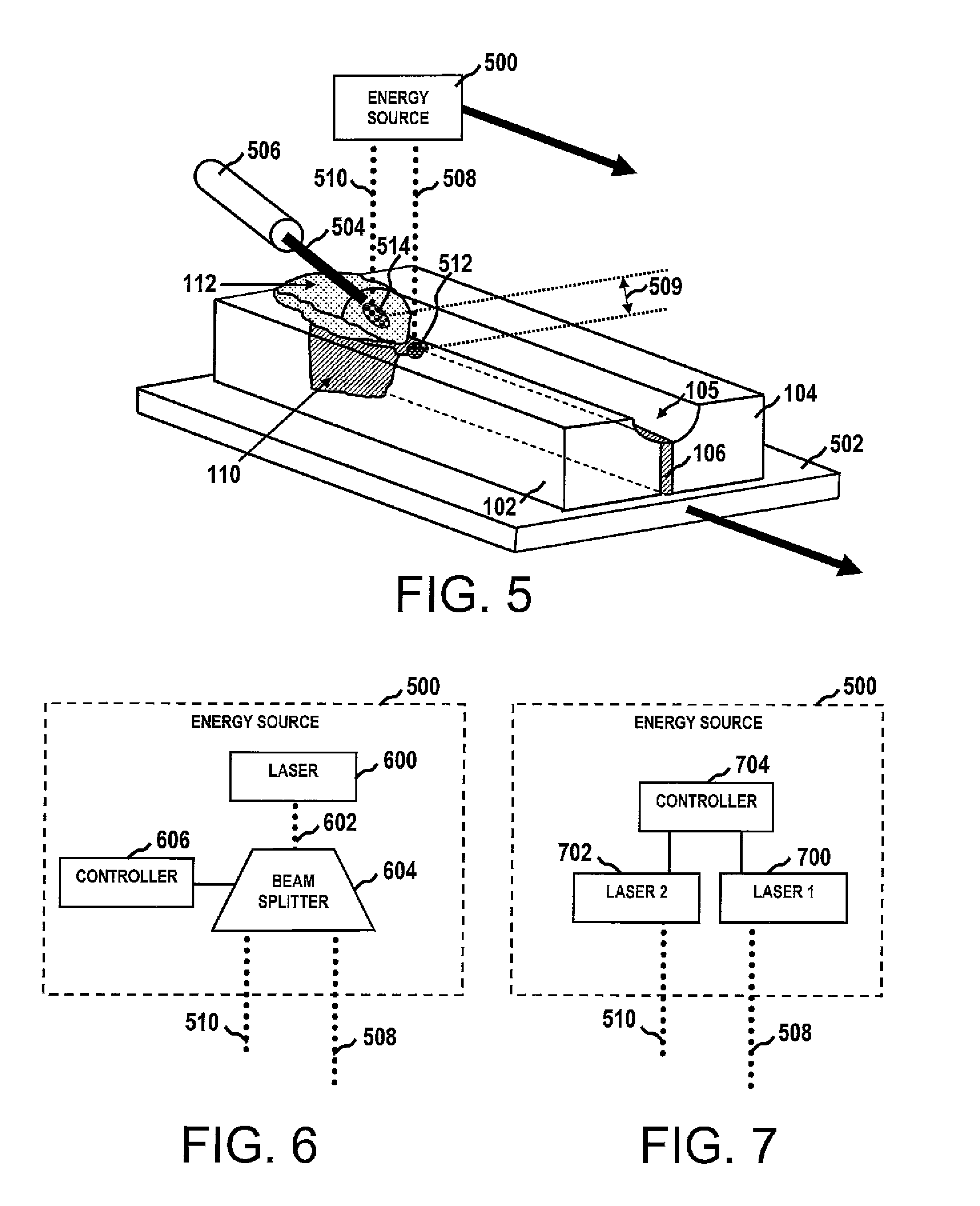
[0022]FIGS. 1-4 show perspective views of two exemplary component assemblies before and after application of the presently disclosed welding techniques. Such figures and the related description discuss welding of first and second components together, altho...


PUM

PropertyMeasurementUnit
Diameteraaaaaaaaaa
Diameteraaaaaaaaaa
Diameteraaaaaaaaaa

Abstract

A system and method for laser beam welding at least two adjacent superalloy components involves substantially simultaneous formation of a base weld with a first filler metal placed between the components and cap weld with second filler metal formed over the base weld. A shim is inserted between the components, which may optionally be formed with a groove along the joint surface. A filler wire is fed to a location over the given surface or within the optional groove. Two lasers or a laser and coupled beam splitter supply first and second laser beams that are applied at focal points separated by a predetermined distance (e.g., 0.05-1.5 cm). The first laser beam is used to form a base weld with the first filler metal between the components, and the second laser beam is used to form a cap weld with the second filler metal on top of the base weld.

Description

FIELD OF THE INVENTION[0001]The subject matter disclosed herein relates to laser beam welding, and more particularly, to a modified laser beam welding system and method for joining superalloy materials or clad metals such as present in gas turbine applications.BACKGROUND OF THE INVENTION[0002]Power generation technologies and related systems, including gas turbine engines, jet engines, wind turbines and related platforms or towers, are often subject to dynamic operating conditions. The potential stresses of such operating conditions, particularly high temperature and pressure conditions, require power generation components having increased strength and durability. One exemplary class of materials that has been developed for use in such environments corresponds to superalloys.[0003]Superalloys are alloys containing about 50% or more by weight of a base metal, including but not limited to nickel, cobalt and iron, to which alloying elements are added to improve the mechanical and physi...

Claims


Application Information

Patent Timeline
IPC IPC(8): B23K26/20
CPCB23K26/0604B23K26/0676B23K26/203B23K26/26B23K26/32F01D5/005B23K2201/18B23K2201/34B23K2203/08B23P6/007B23K2201/001B23K26/211B23K2101/001B23K2101/18B23K2101/34B23K2103/04B23K2103/26Y02T50/60
Inventor NOWAK, DANIEL ANTHONYARNETT, MICHAEL DOUGLASKOTTILINGAM, SRIKANTH CHANDRUDU
Owner GENERAL ELECTRIC CO
Why Eureka
Try Eureka