
Light emitting diode system

a technology of light emitting diodes and diodes, which is applied in the direction of electric variable regulation, process and machine control, instruments, etc., can solve the problems of affecting the operation of modern electronic ballasts or drivers, affecting the operation of the lamp driver, and the life of the respective housing for receiving the respective driver for powering the fluorescent type light source is rather long, so as to achieve stable light output and reduce the effect of operation time and speed up in tim

Active Publication Date: 2011-02-24
KONINKLIJKE PHILIPS ELECTRONICS NV
View PDF9 Cites 30 Cited by
  • Summary
  • Abstract
  • Description
  • Claims
  • Application Information

AI Technical Summary

Benefits of technology

[0008]The light emitting system according to the invention has the advantage, that any modern electronic ballasts or drivers will be able to power the LED retrofit tube since the driver will always sense the presence of a ‘normal’ fluorescent TL-tube. Since thus, the driver will assume the presence of a state of the art TL-tube, the driver will power the LED retrofitting lamp in a stable manner.
[0024]In accordance with a further embodiment of the invention, the light emitting system further comprises means for receiving remote control signals. Including the means for receiving remote control signals into the light emitting system itself has the advantage, that due to the open design of the light emitting system for light emission electromagnetic waves and / or acoustic waves as remote control signals can reach the means for receiving the remote control signals in an unpertubated manner. In case such means for receiving remote control signals would be included into the fluorescent lamp driver, due to a typical encapsulation of the fluorescent lamp driver in a metallic support remote control signals would be shielded from a respective sensor located in the fluorescent lamp driver. Thus, by including such a sensor for receiving remote control signals into the light emitting system itself, an unwanted shielding of remote control signals can be prevented. Such remote control signals may comprise for example signals for changing the light emission characteristics of the light emitting system, like for example color temperature, light intensity, spatial distribution of the light, power on and off etc.

Problems solved by technology

Further, compared to the lifetime of for example fluorescent type light sources, the lifetime of respective housings for receiving the fluorescent type light sources and the respective drivers for powering the fluorescent type light sources is rather long.
However, there is the problem that modern electronic ballasts or drivers have identification capabilities of fluorescent light sources like “TL-tubes”, i.e. they measure for example the filaments resistance in order to detect the type of TL-tube connected to the ballast.
In case an LED retrofit tube is connected to such an intelligent tube driver, due to the presence of LEDs and not simple TL-tube filaments the tube driver might detect a strange filament resistance and hence quit operation.

Method used


Image

  • Light emitting diode system
  • Light emitting diode system
  • Light emitting diode system

Examples


Embodiment Construction

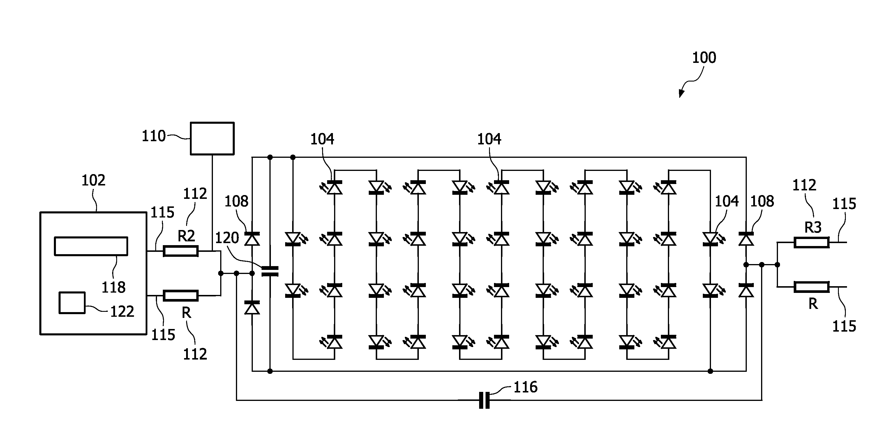
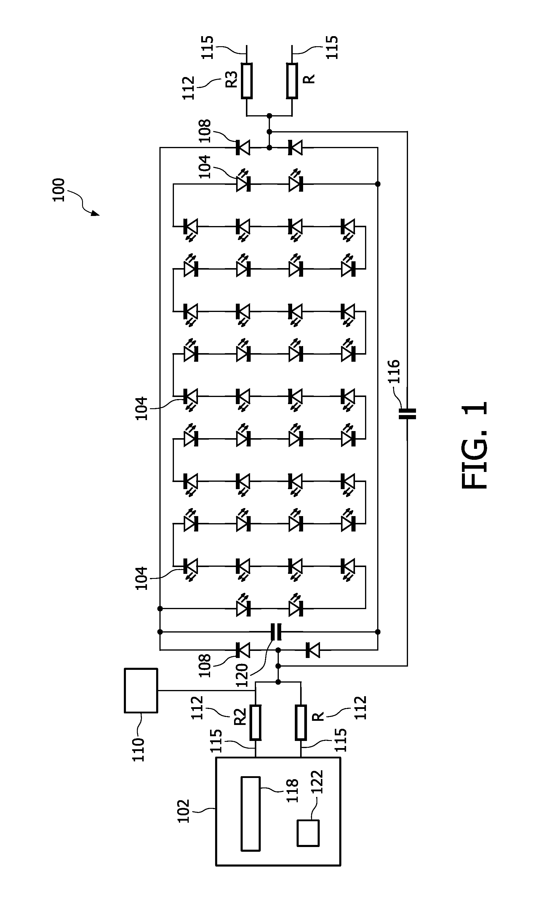
[0034]FIG. 1 is a schematic illustrating a light emitting system 100 according to the invention. The light emitting system comprises a set of serially connected light emitting diodes 104. When retrofitting fluorescent tubes, there are usually four base prongs 115 resent at the tube, two on each side. Traditionally, the two pins on a base cap are used to power the filament. Since in LED tubes no filaments are required electronic components like resistors 112 which are connected to respective base prongs 115 are used to emulate for example the presence of a certain fluorescent lamp filament resistance and / or fluorescent lamp impedance to the fluorescent lamp driver 102. The capacitor 116 being located in between the two sets of base prongs 115 may be an interference suppression capacitor or might be designed to influence the impedance of the tube in the frequency range used by the driver to power the lamp.

[0035]As can be seen from FIG. 1, the two base prongs 115 are connected to the f...


PUM


Abstract

The invention relates to a light emitting system (100), the system comprising a light emitting diode (104), a socket adapter for retrofitting a fluorescent lamp and an electric circuit (112; 200; 306), the electric circuit (112; 200; 306) being adapted for emulating the presence of a fluorescent lamp to a fluorescent lamp driver (102).

Description

FIELD OF THE INVENTION[0001]The invention relates to a light emitting system and a lamp driver for a light emitting system.BACKGROUND OF THE INVENTION[0002]Light emitting diodes (LEDs) will play an increasingly significant role in general lighting in the future. This will result in more and more new installations being equipped with LED light sources in various ways. The reason for replacing state of the art light sources with LED light sources is the low power consumption of LED light sources and their extremely long lifetime.[0003]Further, compared to the lifetime of for example fluorescent type light sources, the lifetime of respective housings for receiving the fluorescent type light sources and the respective drivers for powering the fluorescent type light sources is rather long. Thus, it seems to be attractive if a user could simply replace such kind of fluorescent type light sources.[0004]However, there is the problem that modern electronic ballasts or drivers have identifica...

Claims


Application Information

Patent Timeline
IPC IPC(8): H05B37/02H05B41/36H05B44/00
CPCH05B33/0806Y02B20/386Y02B20/383Y02B20/30H05B45/3578H05B45/14H05B45/305
Inventor RADERMACHER, HARALD JOSEF GUNTHER
Owner KONINKLIJKE PHILIPS ELECTRONICS NV
Learn More