
Direct conversion receiver

a direct conversion and receiver technology, applied in the field of wireless communication, can solve the problems of limiting the overall performance of the receiver based on such technology, unable to provide the opposite sideband (“image”) suppression, and unable to provide the rejection of analog phasing networks

Inactive Publication Date: 2011-02-24
YOUNGBLOOD GERALD
View PDF27 Cites 18 Cited by
  • Summary
  • Abstract
  • Description
  • Claims
  • Application Information

AI Technical Summary

Problems solved by technology

However, simple direct conversion receivers suffer from the lack of opposite sideband (“image”) suppression when the signal is mixed to direct current (DC) (i.e., zero Hertz).
This problem results from the signal of interest and the image products being superimposed in the baseband output.
The image rejection provided by analog phasing networks in conjunction an image reject mixer is limited, which limits overall performance of receivers based on such technology.
Image rejection mixers that use individual mixers are complex in implementation and typically exhibit on the order of 7-8 dB of conversion loss.
Such mixers typically require very high level local oscillator drive power to achieve large signal handling capability and have poor local oscillator to input port isolation.
Further, their performance is very sensitive to output impedance variations and offer poor termination to the preceding analog stage.
While addressing the conversion loss problem, image reject mixers using the quadrature sampling detector method as described by van Graas in the September 1990 QEX article and in U.S. Pat. No. 6,230,000, issued to Tayloe, suffer from increasing noise figure and local oscillator radiation with frequency and poor impedance matching.
To perform adequately above approximately 15-20 MHz, such designs have typically required prior stage radio frequency amplifiers that in turn limit total spurious free dynamic range and increase power consumption.
Since the input signal causes the FET source voltage to swing around the bias voltage, the gate to source voltage will in turn be modulated thus introducing distortion.
Another disadvantage of applying bias to the analog switches is that any direct current offset voltage between the switches will increase local oscillator radiation.
Thus, existing quadrature sampling detectors exhibit shortcomings that are increasingly undesirable as expectations of performance of wireless devices continue to rise.

Method used


Image

  • Direct conversion receiver
  • Direct conversion receiver
  • Direct conversion receiver

Examples


Embodiment Construction

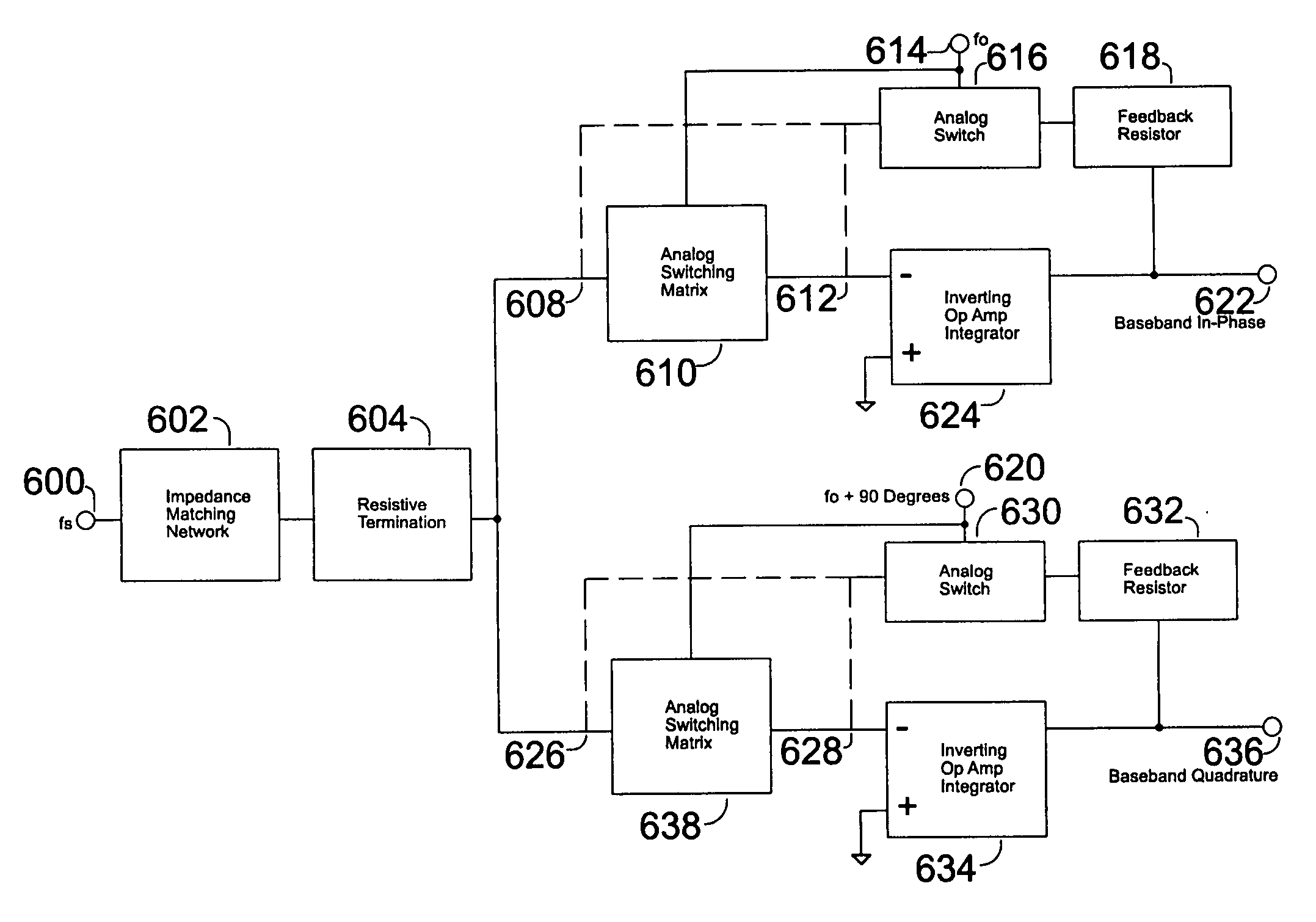
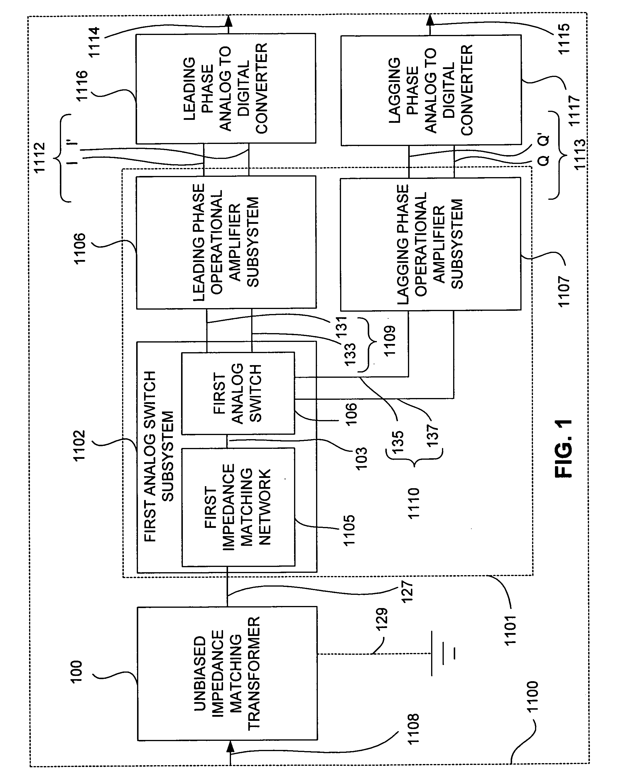
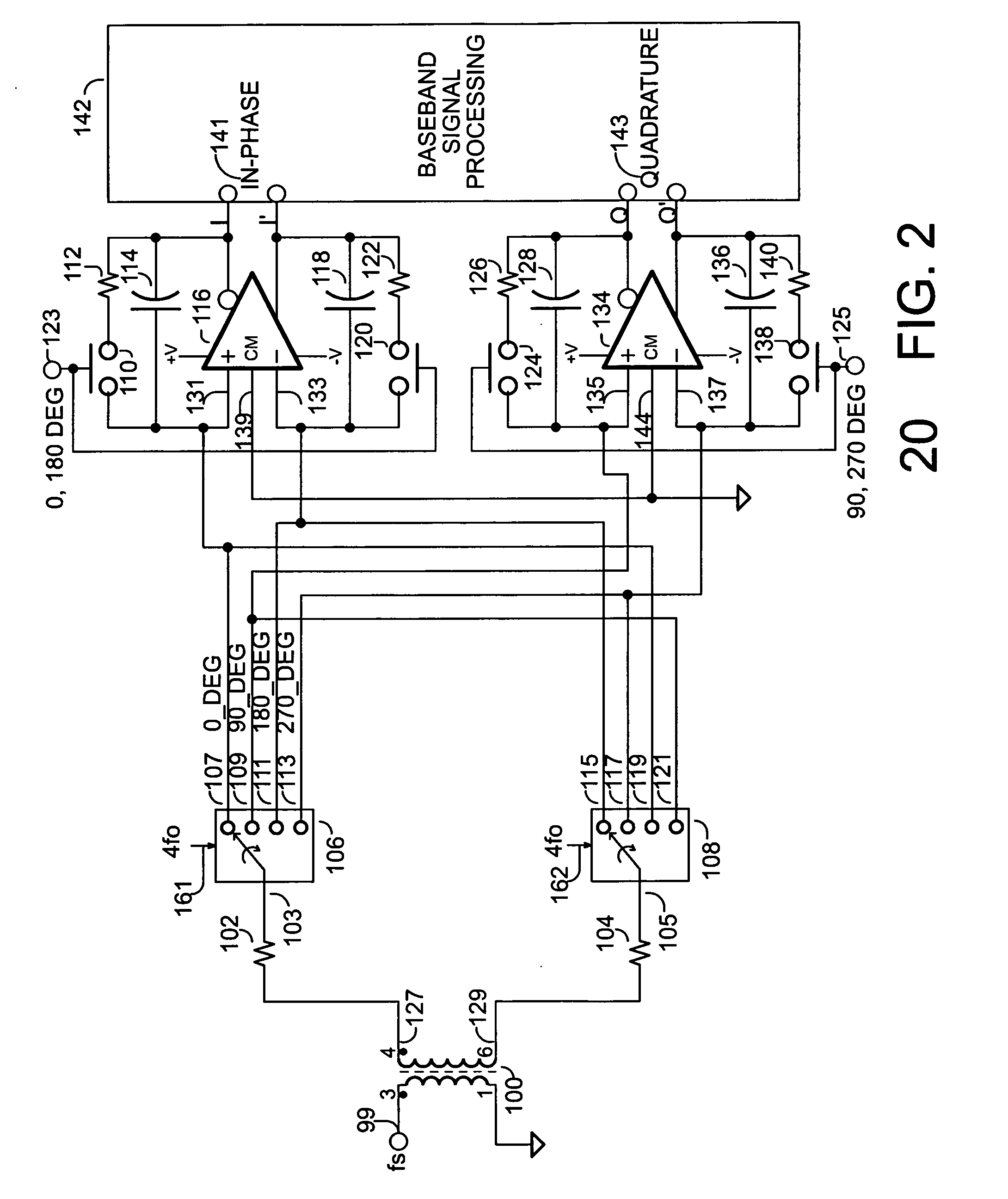
[0028]Apparatus is provided for a direct conversion receiver. In accordance with at least one embodiment, the apparatus providing the direct conversion receiver comprises a phase sampling detector (e.g., a Quadrature Sampling Detector), which comprises a leading phase operational amplifier subsystem and a leading phase analog switch, as well as a lagging phase operational amplifier subsystem and a lagging phase analog switch. In accordance with at least one embodiment, a leading phase analog switch output terminal is coupled to a first leading phase operational amplifier input of the leading phase operational amplifier subsystem, and the leading phase analog switch output terminal is maintained continually at a ground potential.

[0029]In accordance with at least one embodiment, a lagging phase analog switch output terminal is coupled to a first lagging phase operational amplifier input of the lagging phase operational amplifier subsystem, and the lagging phase analog switch output te...


PUM


Abstract

In accordance with at least one embodiment, apparatus providing a direct conversion receiver comprises a phase sampling detector (e.g., a quadrature sampling detector), which comprises a leading phase operational amplifier subsystem and a leading phase analog switch, as well as a lagging phase operational amplifier subsystem and a lagging phase analog switch. In accordance with at least one embodiment, a leading phase analog switch output terminal is coupled to a first leading phase operational amplifier input of the leading phase operational amplifier subsystem, and the leading phase analog switch output terminal is maintained continually at a ground potential. In accordance with at least one embodiment, at least one of element selected from a group consisting of: a resistor feedback switch, a commutating input switch in a resistive feedback loop, a differential capacitor, an unbiased analog switch input terminal, and an unbiased analog switch output terminal is provided.

Description

CROSS-REFERENCE TO RELATED APPLICATIONS[0001]This application claims the benefit of U.S. Provisional Application No. 61 / 274,612, filed Aug. 18, 2009.BACKGROUND OF THE INVENTION[0002](1) Field of the Invention[0003]This invention relates to the general field of wireless communications and more specifically, the conversion of signals in frequency.[0004](2) Description of the Related Art[0005]Direct conversion (DC) or homodyne radio receivers have been well known for decades and are widely used in modern day communications systems. However, simple direct conversion receivers suffer from the lack of opposite sideband (“image”) suppression when the signal is mixed to direct current (DC) (i.e., zero Hertz). This problem results from the signal of interest and the image products being superimposed in the baseband output. Image reject mixers have been used in an attempt to address the image problem associated with simple direct conversion mixers. The image rejection provided by analog phasi...

Claims


Application Information

Patent Timeline
Patent Type & Authority Applications(United States)
IPC IPC(8): H03F3/68
CPCH03D7/1441H03D7/1458H03D7/165H04B1/30H03D2200/0043H03D7/1483H03D7/1491H03D2200/0023H03D7/1466
Inventor YOUNGBLOOD, GERALD
Owner YOUNGBLOOD GERALD
Learn More