
Method of producing a patterned birefringent product

a technology of patterned birefringent and product, which is applied in the direction of printing, optics, instruments, etc., can solve the problems of poor heat resistance, the birefringence of the portion will end up decreasing, and it is extremely difficult to create patterns at a resolution lower than the thickness of the film, so as to achieve high heat resistance and resolution.

Active Publication Date: 2011-02-24
FUJIFILM CORP
View PDF3 Cites 28 Cited by
  • Summary
  • Abstract
  • Description
  • Claims
  • Application Information

AI Technical Summary

Benefits of technology

[0026]By the method of the present invention and the builder according to the present invention, a patterned birefringent product high in resolution and heat-resistance can be obtained. The birefringence pattern is readily pattern-identifiable when observed through a polarizing plate, whereas it is almost transparent and colorless when observed through no polarizing plate, and the birefringence pattern is effective for preventing forgery and for imparting visual effects. In particular, it is possible to reduce the number of production steps and thus the production cost if such a transferring material is used.MODE FOR CARRYING OUT INVENTION
[0027]Some examples of preferable modes of the present invention are described below in detail.
[0028]In the present specification, “to” denotes a range including numerical values described before and after it as a minimum value and a maximum value.
[0029]Herein, in the present specification, the term retardation or Re means an in-plane retardation, and the term Re(λ) indicates an in-plane retardation at wavelength λ (nm). The in-plane retardation (Re(λ)) can be measured by making light of wavelength λ, nm incident in the direction of the normal of the film, in KOBRA 21ADH or WR (each trade name, manufactured by Oji Scientific Instruments). In the present specification, retardation or Re means one measured at wavelength λ, is 611±5 nm, 545±5 nm and 435±5 nm for R, G, and B, respectively, and denotes one measured at wavelength λ 545±5 nm or 590±5 nm unless otherwise specified any of color.
[0030]It is to be noted that, regarding angles, the term “substantially” in the context of this specification means that a tolerance of less than ±5° with respect to the precise angles can be allowed. Difference from the precise angles is preferably less than 4°, and more preferably less than 3°. It is also to be noted that, regarding retardation values, the term “substantially” in the context of the specification means that a tolerance of less than ±5% with respect to the precise values can be allowed. It is also to be noted that the term “The Re value is substantially not zero” in the context of the specification means that the Re value is not less than 5 nm. The measurement wavelength for refractive indexes is any visible light wavelength, unless otherwise specified. It is also to be noted that the term “visible light” in the context of the specification means light of a wavelength falling within the range from 400 to 700 nm.(Birefringence Pattern Builder)
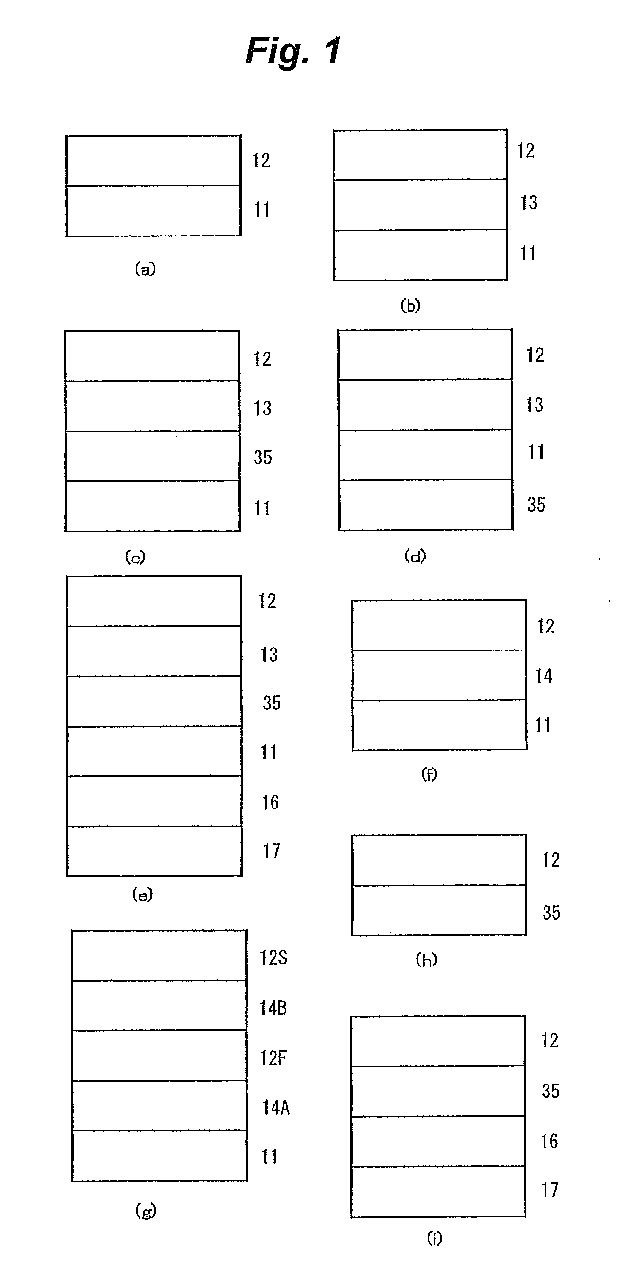
[0031]FIGS. 1(a) to 1(i) are schematic sectional views showing several examples of the birefringence pattern builder. The birefringence pattern builder is a material for preparing birefringence pattern, and a material with which the patterned birefringent product can be prepared by conducting the predetermined steps. The birefringence pattern builder shown in FIG. 1(a) is an example having an optically anisotropic layer 12 on a support (substrate) 11. The birefringence pattern builder shown in FIG. 1(b) is an example having an alignment layer 13. The alignment layer 13 functions as a layer for supporting the alignment / orientation of liquid crystalline compounds, when use is made, as the optically anisotropic layer 12, of a layer formed by coating a substrate with a solution comprising the liquid crystalline compounds and drying the solution to thereby form a liquid crystal phase, and then polymerizing and fixing the compounds by applying heat or irradiating ionized radiation to the liquid crystal phase.

Problems solved by technology

However, patterns produced by techniques in which birefringence is reduced with heat, as set forth above, all have the drawback of poor heat resistance.
That is, there is a risk that when heat is applied to a portion in which birefringence remains, the birefringence of that portion will end up decreasing.
Further, in techniques employing thermal heads or the like, since it is difficult to impart difference between the thermal conductivity in the direction of thickness and the thermal conductivity in the in-surface direction, it is extremely difficult to create a pattern at a resolution lower than the thickness of the film.
Heating with a laser permits the creation of high-resolution patterns, but there is a problem in that the drawing of fine patterns by scanning with a laser is time-consuming.
However, the resistance to light of the pattern that is produced by this technique is low, rendering the pattern unsuitable as a birefringence pattern for use in optical elements in particular.
However, in this method, controlling the state of alignment of the liquid crystals prior to fixation requires conducting multiple exposures while carefully controlling the temperature of the overall system, presenting a problem in the form of a demanding manufacturing process.

Method used


Image

  • Method of producing a patterned birefringent product
  • Method of producing a patterned birefringent product
  • Method of producing a patterned birefringent product

Examples


example 1

Preparation of Birefringent Pattern Builder and Preparation of Birefringent Samples Having a Desired Retardation by Using the Same

(Preparation of Coating Liquid CU-1 for Dynamic Property Control Layer)

[0156]The composition below was prepared, filtered through a polypropylene filter having a pore size of 30 μm, and the filtrate was used as coating liquid CU-1 for forming a dynamic property control layer.

[0157]B-1 was a copolymer of methyl methacrylate, 2-ethylhexyl acrylate, benzyl methacrylate and methacrylic acid, having a copolymerization composition ratio (molar ratio) of 55 / 30 / 10 / 5, a mass-average molecular mass of 100,000, and a Tg of about 70° C.

[0158]B-2 was a copolymer of styrene and acrylic acid having a copolymerization composition ratio (molar ratio) of 65 / 35, a mass-average molecular mass of 10,000, and a Tg of about 100° C.

Composition of Coating Liquidfor Dynamic Property Control Layer(% by mass)Binder (B-1)5.89Binder (B-2)13.74BPE-500 (trade name, manufactured by Shin-...

example 2

Preparation of Birefringent Samples of which the Relationship Between Exposure Quantity and Post-Baking Retardation was Adjusted by Modification of the Concentration of the Photopolymerization Initiator in the Adhesive Layer for Transfer

(Preparation of Coating Liquids AD-2 and AD-3 for Adhesive Layer for Transfer)

[0171]Coating Liquids AD-2 and AD-3 for adhesive layer for transfer, in which the concentration of the photopolymerization initiator was altered from that in AD-1, were newly prepared and used after they were filtered through a polypropylene filter having a pore size of 0.2 μm. The formulations of AD-2 and AD-3 as well as that of AD-1 for comparison are shown in Table 3. The formulation AD-2 had a photopolymerization initiator concentration lower, while the formulation AD-3 had a photopolymerization initiator concentration higher than that of the formulation AD-1.

TABLE 3Name of formulationComposition of coating liquid (% by mass)AD-1AD-2AD-3Binder (B-3)8.058.098.01KAYARAD D...

example 3

Preparation of Birefringent Samples of which the Relationship Between the Exposure Quantity and the Post-Baking Retardation is Modified According to the Kind of The Photopolymerization Initiator in the Adhesive Layer for Transfer

(Preparation of Coating Liquid AD-4 for Adhesive Layer for Transfer)

[0179]Coating liquid AD-4 for adhesive layer for transfer, in which the kind of the photopolymerization initiator was altered from that in AD-1, was newly prepared and used after it was filtered through a polypropylene filter having a pore size of 0.2 μm. The formulation of AD-4 and that of AD-1 for comparison are shown in Table 6.

[0180]As RPI-2, use was made of 2,4-bis(trichloromethyl)-6-[4-(N,N-diethoxycarbonylmethyl)-3-bromophenyl]-s-triazine.

TABLE 6Name of formulationComposition of coating liquid (% by mass)AD-1AD-4Binder (B-3)8.058.09KAYARAD DPHA (trade name, manufactured by4.834.85Nippon Kayaku)Radical photopolymerization initiator (RPI-1)0.12—Radical photopolymerization initiator (RPI...


PUM

PropertyMeasurementUnit
wavelengthaaaaaaaaaa

Abstract

A method of producing a patterned birefringent product, containing at least steps (I) to (III) in this order:(I) providing a birefringent pattern builder having an optically anisotropic layer containing a polymer;(II) subjecting two or more regions of the birefringent pattern builder to exposure to light under exposure conditions different from each other; and(III) heating a laminated structure obtained after the step (II) at 50° C. or higher and 400° C. or lower.

Description

TECHNICAL FIELD[0001]The present invention relates to a method of producing a patterned birefringent product and to a patterned birefringent product produced by said method.BACKGROUND ART[0002]There are proposed several methods of producing birefringence patterns. JP-A-3-141320 (“JP-A” means unexamined published Japanese patent application) discloses use of a patterned birefringent product possibly visualized as it is held between two polarization plates in a method of recording an image. In JP-A-3-141320, use is made of a technique using a heat mode laser or thermal head to apply heat to the image-forming portion of an anisotropic film, thereby completely or partially reducing the anisotropy.[0003]However, patterns produced by techniques in which birefringence is reduced with heat, as set forth above, all have the drawback of poor heat resistance. That is, there is a risk that when heat is applied to a portion in which birefringence remains, the birefringence of that portion will e...

Claims


Application Information

Patent Timeline
Patent Type & Authority Applications(United States)
IPC IPC(8): G02F1/03G03B27/32
CPCB44F1/10G02F2413/09G02F2001/133633G02B5/3016G02F1/133631G02F1/133633
Inventor KANEIWA, HIDEKIAMIMORI, ICHIRO
Owner FUJIFILM CORP
Learn More