
Bridge structural safety monitoring system and method thereof

a safety monitoring and bridge technology, applied in bridges, instruments, bridges, etc., can solve the problems of bridge damage, no method can provide a structural damage report timely/anytime, early warning or in-time warning, and damage to bridges, so as to reduce labor requirements and avoid inspectors from being exposed

Inactive Publication Date: 2011-02-24
NAT APPLIED RES LAB
View PDF4 Cites 52 Cited by
  • Summary
  • Abstract
  • Description
  • Claims
  • Application Information

AI Technical Summary

Benefits of technology

[0036]Another objective of the present invention is to provide a bridge structural safety monitoring system to replace a regular visual inspection method, so as to lower the labor requirement, and avoid inspectors from being exposed in dangerous areas.
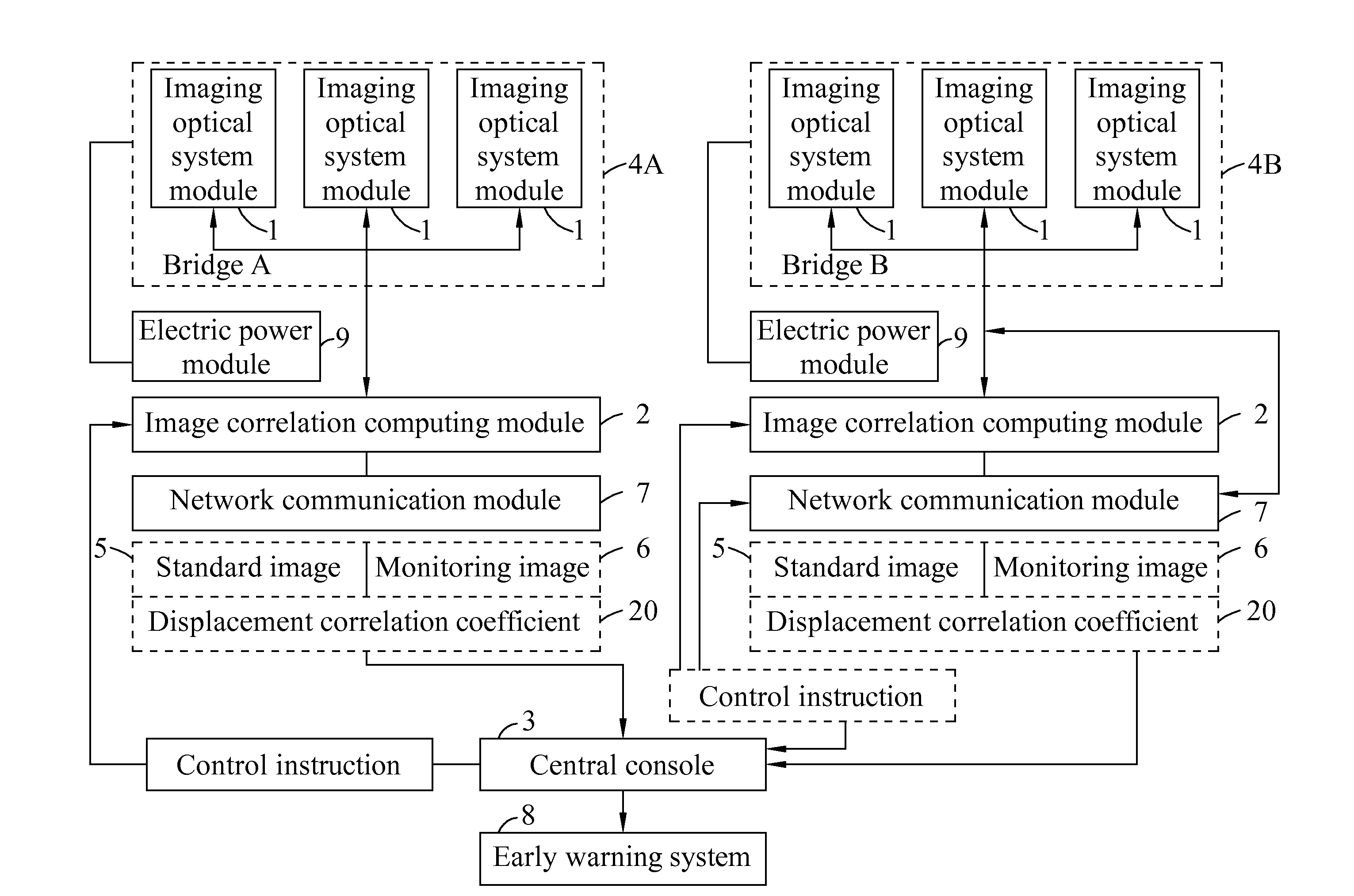
[0037]To achieve the foregoing primary objective, the present invention provides a bridge structural safety monitoring system, comprising an imaging optical system module, an image correlation computing module, a network communication module and a central console. The imaging optical system module is located (constructed) in the bridge site for imaging a standard image of a monitoring area of a bridge operated at normal conditions, and taking photos of the monitoring area of the bridge continuously to obtain a series monitoring images of the monitoring area of the bridge, and the image correlation computing module uses an image data comparison method to compute the standard image and the monitoring images to obtain a displacement correlation coefficient of a relative displacement among structures of the bridge, and the network communication module transmits the displacement correlation coefficient to the central console, such that the structural report of the bridge can be obtained timely / anytime.
[0041]The image correlation computing module adopts a characteristic sampling method to monitor key positions, and these characteristics correspond to the characteristics of the human visual method and simulate each evaluation standard in the evaluation guideline according to the value of the displacement correlation coefficient to create a database, and such database can replace the regular visual method, so as to achieve the effect of reducing the labor requirement and avoiding the inspectors from being exposed to the dangerous area.
[0043]using an imaging optical system module to obtain at least one standard image of at least one monitoring area of a bridge at a normal operation condition; using the imaging optical system module to take photos of each monitoring area continuously to obtain a plurality of monitoring images of the monitoring area; using an image correlation computing module and an image data comparison method to compare the standard image with each the monitoring image, so as to obtain a displacement correlation coefficient of a relative displacement among structures of the bridge; andtransmitting the displacement correlation coefficient to a central console, so that the structural report of the bridge can be obtained timely / anytime.
[0044]In summation, the bridge structural safety monitoring system of the present invention has the following advantages:

Problems solved by technology

The destructive inspection exerts a pressure or a pulling force at a portion of the structure to create a destructive effect to test a structural strength.
In the aforementioned methods, bridges are examined passively according to the laws and regulations, and none of the methods can provide a structural damage report timely / anytime or provide an early warning or in-time warning.
In an extreme weather condition (such as a typhoon or a heavy storm) or after an earthquake occurs, the bridge may be damaged seriously and cannot be inspected visually timely.
Particularly, in the extreme weather condition, the engineers and technicians are unable to reach the site to inspect the bridge or provide an early warning when the bridge could be seriously damaged, and it may result in an injury of the citizen and the property loss.

Method used


Image

  • Bridge structural safety monitoring system and method thereof
  • Bridge structural safety monitoring system and method thereof
  • Bridge structural safety monitoring system and method thereof

Examples


Embodiment Construction

[0059]The technical characteristics of the present invention will become apparent with the detailed description of the following preferred embodiments and related drawings.

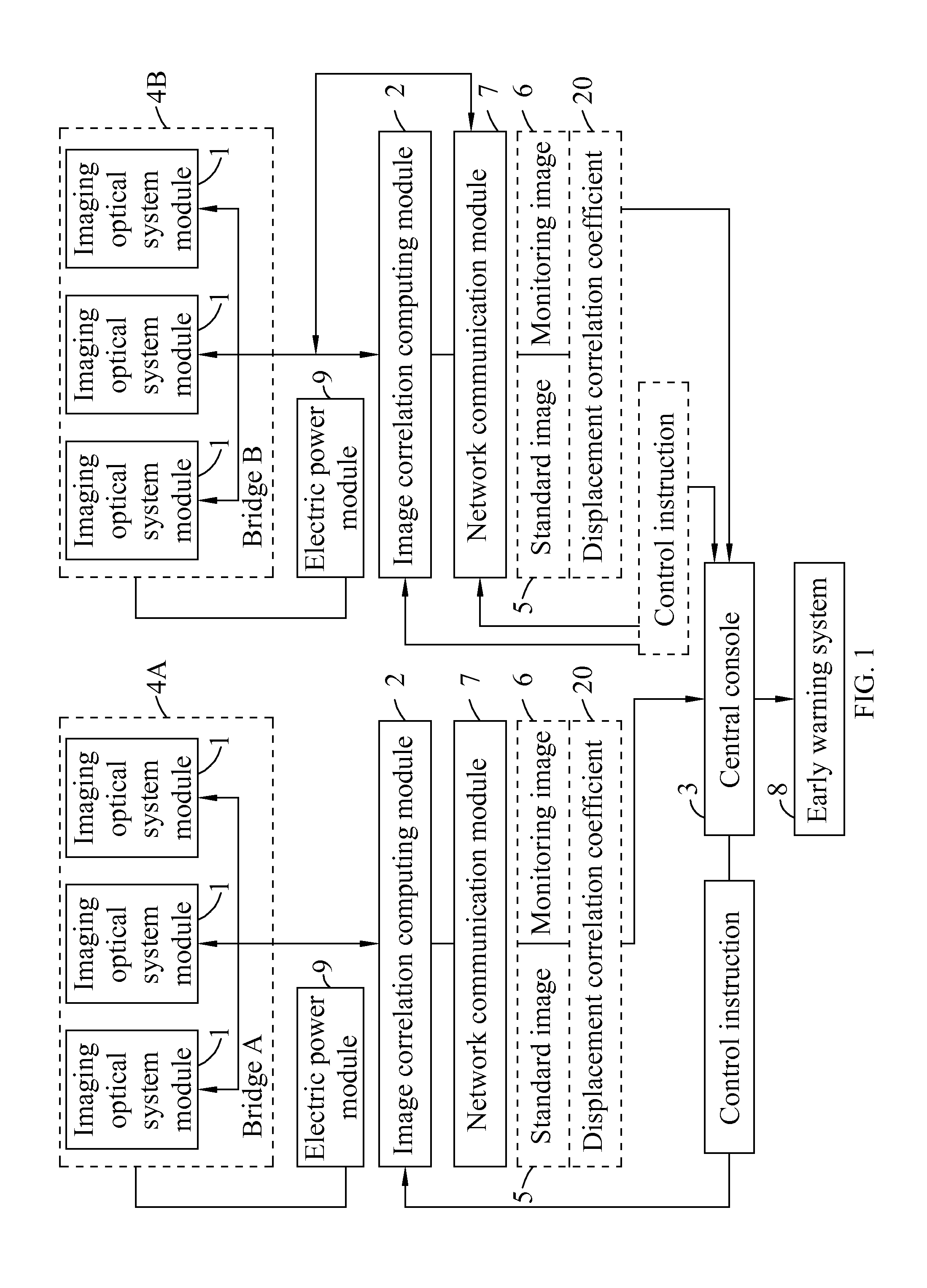
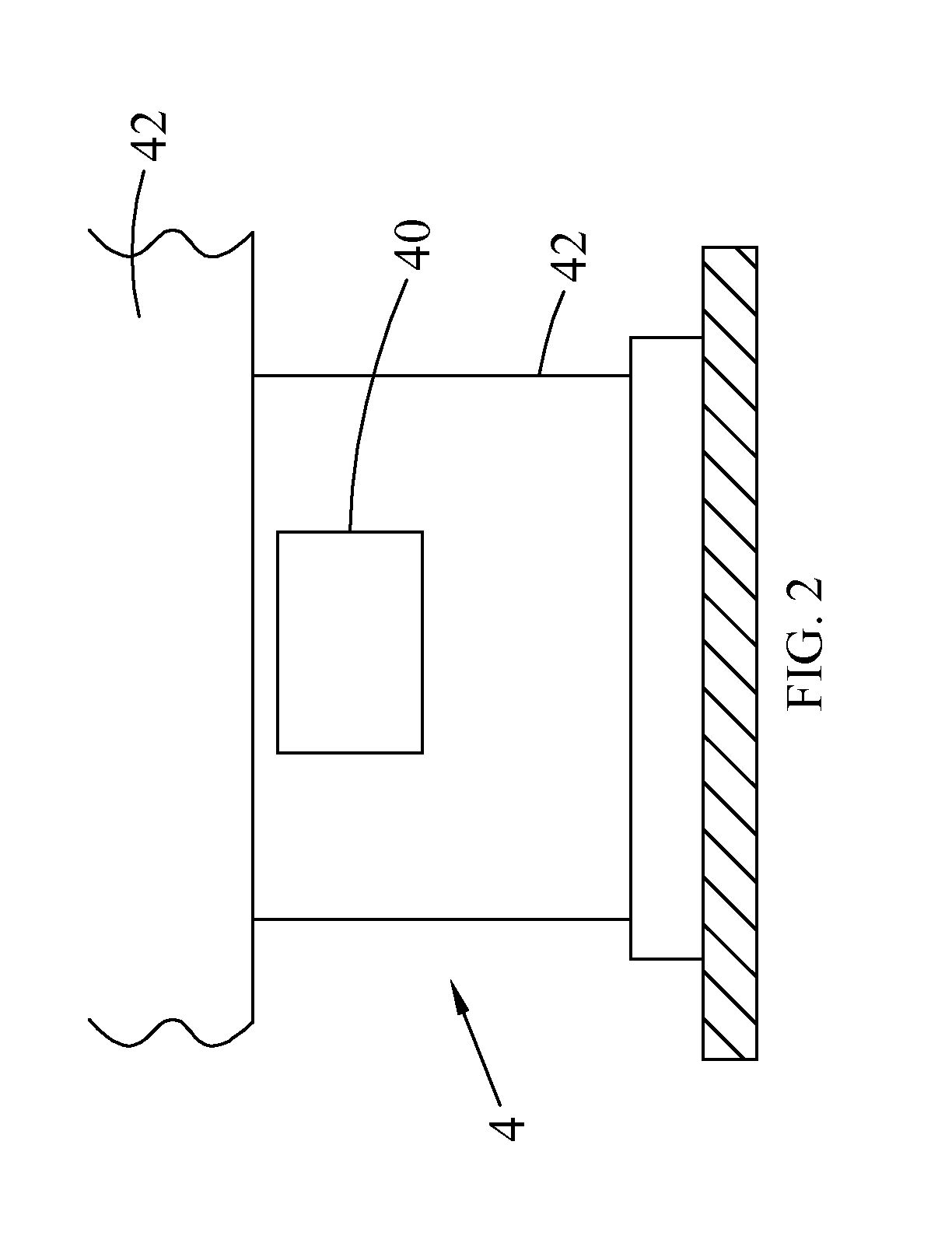
[0060]With reference to FIG. 1 for schematic structural diagram of a bridge structural safety monitoring system in accordance with the present invention, the system is construction among at least one imaging optical system module 1, an image correlation computing module 2 and a central console 3. Each imaging optical system module 1 captures images of a bridge A 4A and a bridge B 4B of a monitoring area 40 respectively (as shown in FIG. 2) to create a standard image 5 of a bridge 4 operated at normal conditions (as shown in FIG. 3), and continuously capture images of the monitoring area 40 to obtain a monitoring image 6 (as shown in FIG. 4). The image correlation computing module 2 compares the standard image 5 with the monitoring image 6 to obtain a displacement correlation coefficient 20 of the monitoring area 4...


PUM


Abstract

The present invention discloses a bridge structural safety monitoring system and a bridge structural safety monitoring method. The method includes the steps of capturing an image of a monitoring area of a bridge to create a standard image of the bridge operated at normal conditions, capturing images of the monitoring area of the bridge continuously to obtain monitoring images, comparing the standard image with the monitoring image to obtain a displacement correlation coefficient of the monitoring area of the bridge, and transmitting the displacement correlation coefficient to a central console, such that the central console can determine the using condition of the bridge according to the displacement correlation coefficient.

Description

BACKGROUND OF THE INVENTION[0001]1. Field of the Invention[0002]The present invention relates to a monitoring system, in particular to a monitoring system applied for monitoring a bridge structural safety.[0003]2. Description of the Related Art[0004]As bridge inspection is a continuous ongoing job, and the inspection is divided into the following two types according to its purpose:[0005]1. A timely inspection for monitoring a situation such as a water level or an exposure extent of a bridge pier timely provides the current situation prior to the occurrence of a disaster or an emergency situation.[0006]2. A periodical inspection for testing factors such as deformation, displacement, force distribution, appearance damage or material deterioration that may affect or change a bridge system.[0007]At present, the bridge inspection methods adopted by Taiwan, R.O.C. for daily inspections are divided into the following three kinds in accordance with the Maintenance Manual for Railways and Br...

Claims


Application Information

Patent Timeline
Patent Type & Authority Applications(United States)
IPC IPC(8): G06K9/00
CPCG06K9/00G06T7/0004E01D22/00G06T2207/10016G06T2207/30164G06T7/001
Inventor HUANG, CHI-HUNGCHIANG, WEI-CHIEHLIAO, TAI-SHANHSU, CHIA-WEIWEN, JEN-YUWEI, TZU-HSUANCHEN, YUNG-HSIANG
Owner NAT APPLIED RES LAB
Learn More