
System and method for depth map extraction using region-based filtering

a filtering and depth map technology, applied in image analysis, image enhancement, instruments, etc., can solve the problems of too slow methods and more accurate methods, and achieve the effects of reducing artifacts, reducing artifacts, and increasing filter strength

Inactive Publication Date: 2011-02-24
THOMSON LICENSING INC
View PDF7 Cites 54 Cited by
  • Summary
  • Abstract
  • Description
  • Claims
  • Application Information

AI Technical Summary

Benefits of technology

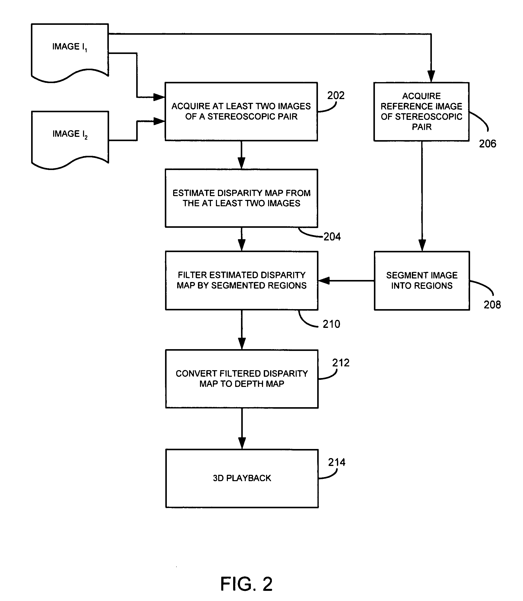
"The present patent provides a system and method for extracting depth information from two images using region-based filtering to reduce artifacts. The method includes acquiring the two images, estimating the disparity of points in the first image with corresponding points in the second image to generate a disparity map, segmenting the first or second image into regions, and filtering the disparity map based on the segmented regions. The filtering includes filtering in both the horizontal and vertical directions, with more filter strength along the vertical direction to reduce stripe artifacts without blurring the depth boundaries. The system and method can be used to extract depth information from stereoscopic images and create a depth map by inverting the estimated disparity for each point. The technical effects of the patent include reducing artifacts and improving the accuracy of depth information extraction from images."

Problems solved by technology

More accurate methods are usually more computationally expensive.
Some of the methods are too slow to be useful for practical applications.
However, the main drawback of the scanline algorithms or functions is that the scanline algorithms or functions often yield horizontal stripe artifacts (see FIG. 5B where stripe artifacts are encircled), because unlike other expensive algorithms such as belief propagation, scanline algorithms only perform optimization one scanline at a time, consequently smoothness constraints are not imposed along vertical directions.

Method used


Image

  • System and method for depth map extraction using region-based filtering
  • System and method for depth map extraction using region-based filtering
  • System and method for depth map extraction using region-based filtering

Examples


Embodiment Construction

[0023]It should be understood that the elements shown in the FIGS. may be implemented in various forms of hardware, software or combinations thereof. Preferably, these elements are implemented in a combination of hardware and software on one or more appropriately programmed general-purpose devices, which may include a processor, memory and input / output interfaces.

[0024]The present description illustrates the principles of the present disclosure. It will thus be appreciated that those skilled in the art will be able to devise various arrangements that, although not explicitly described or shown herein, embody the principles of the disclosure and are included within its spirit and scope.

[0025]All examples and conditional language recited herein are intended for pedagogical purposes to aid the reader in understanding the principles of the disclosure and the concepts contributed by the inventor to furthering the art, and are to be construed as being without limitation to such specifical...


PUM


Abstract

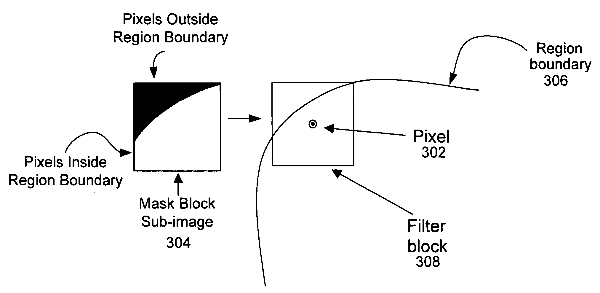
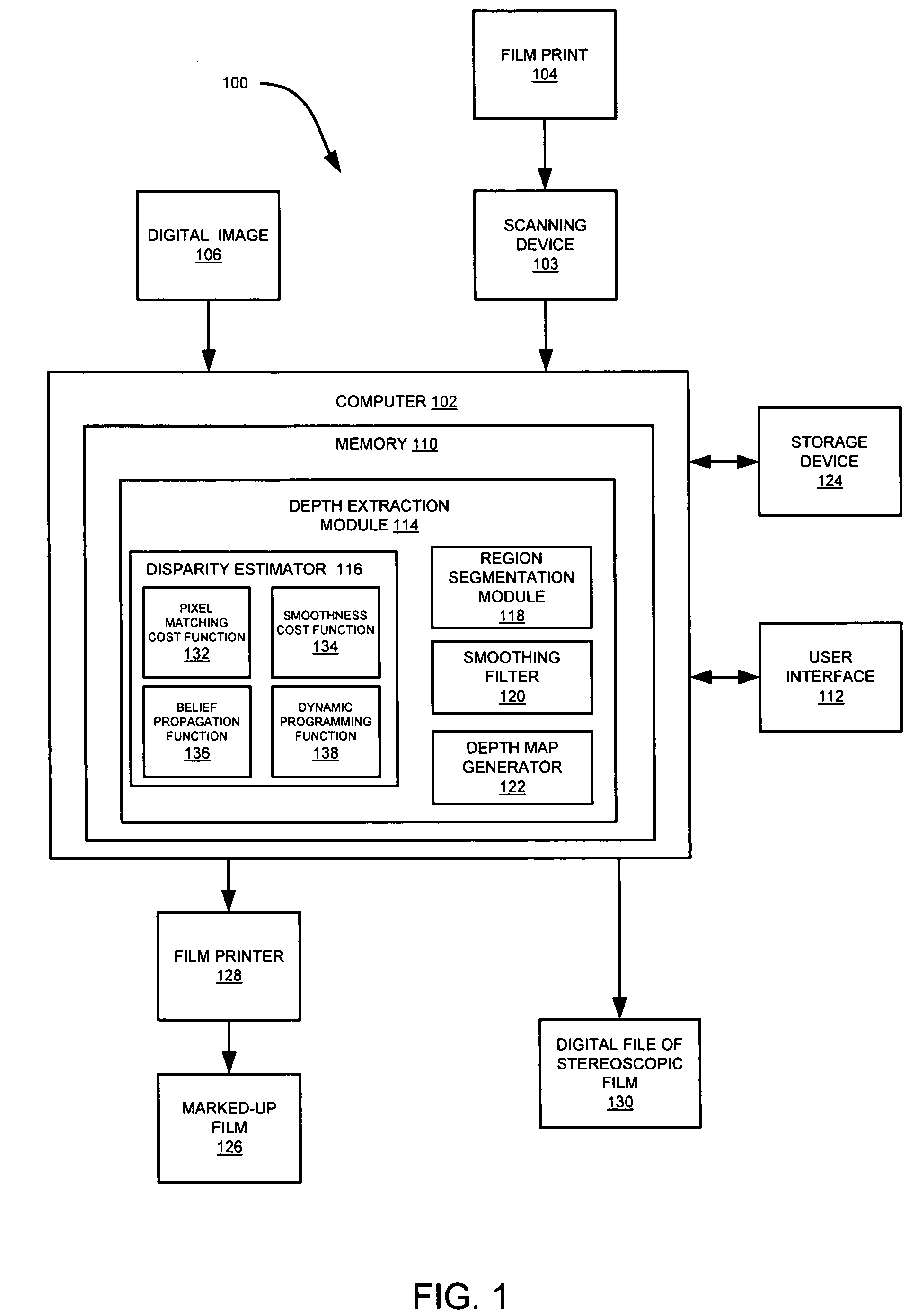
A system and method for extracting depth information from at least two images employing region-based filtering for reducing artifacts are provided. The present disclosure provides a post-processing algorithm or function for reducing the artifacts generated by scanline Dynamic Programming (DP) or other similar methods. The system and method provides for acquiring a first image and a second image from a scene, estimating the disparity of at least one point in the first image with at least one corresponding point in the second image to generate a disparity map, segmenting at least one of the first or second images into at least one region, and filtering the disparity map based on the segmented regions. Furthermore, anisotropic filters are employed, which have a great smoothing effect along the vertical direction than that of the horizontal direction, and therefore, reduce stripe artifacts without significantly blurring the depth boundaries.

Description

TECHNICAL FIELD OF THE INVENTION[0001]The present disclosure generally relates to computer graphics processing and display systems, and more particularly, to a system and method for extracting depth information from at least two images employing region-based filtering for reducing artifacts.BACKGROUND OF THE INVENTION[0002]Stereoscopic imaging is the process of visually combining at least two images of a scene, taken from slightly different viewpoints, to produce the illusion of three-dimensional depth. This technique relies on the fact that human eyes are spaced some distance apart and do not, therefore, view exactly the same scene. By providing each eye with an image from a different perspective, the viewer's eyes are tricked into perceiving depth. Typically, where two distinct perspectives are provided, the component images are referred to as the “left” and “right” images, also know as a reference image and complementary image, respectively. However, those skilled in the art will...

Claims


Application Information

Patent Timeline
Patent Type & Authority Applications(United States)
IPC IPC(8): G06K9/40
CPCG06T7/0075G06T7/0081G06T2207/10012G06T5/002H04N13/0022G06T5/50G06T2207/10028G06T7/593G06T7/11H04N13/128G06T5/70
Inventor ZHANG, DONG-QINGIZZAT, IZZAT
Owner THOMSON LICENSING INC
Learn More