Power-supply device

a power supply and power supply technology, applied in the direction of coupling device connection, sustainable manufacturing/processing, cell components, etc., can solve the problem of increasing the amount of resin material used for the plate b>909/b>

Inactive Publication Date: 2011-02-24
YAZAKI CORP
View PDF6 Cites 59 Cited by
  • Summary
  • Abstract
  • Description
  • Claims
  • Application Information

AI Technical Summary

Benefits of technology

[0026]These and other objects, features, and advantages of the present invention will become more apparent upon reading of the following detailed description along with the accompanied drawings.

Problems solved by technology

Accordingly, there is a problem that a used amount of resin material for the plate 909 is increased.

Method used


Image

  • Power-supply device
  • Power-supply device
  • Power-supply device

Examples


first embodiment

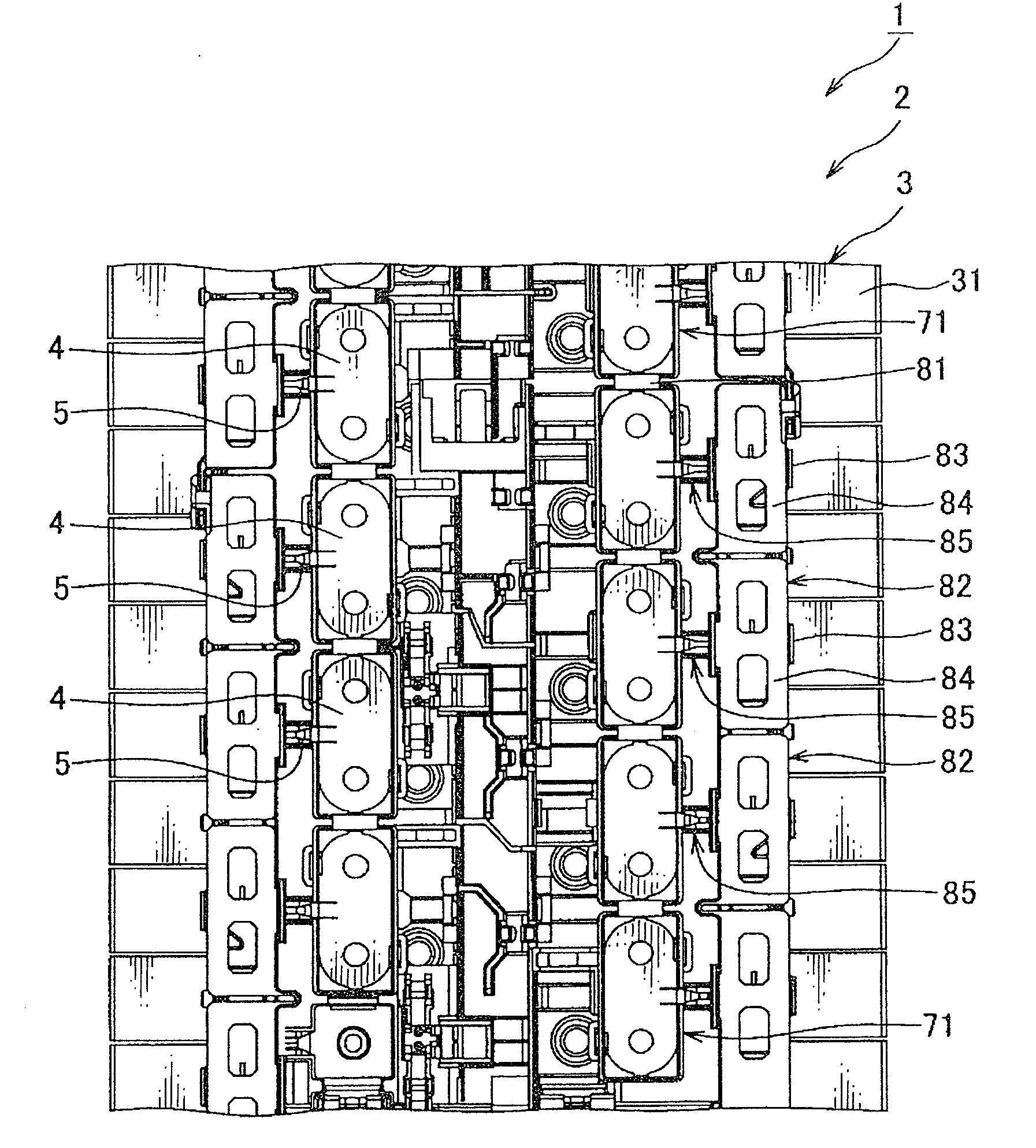
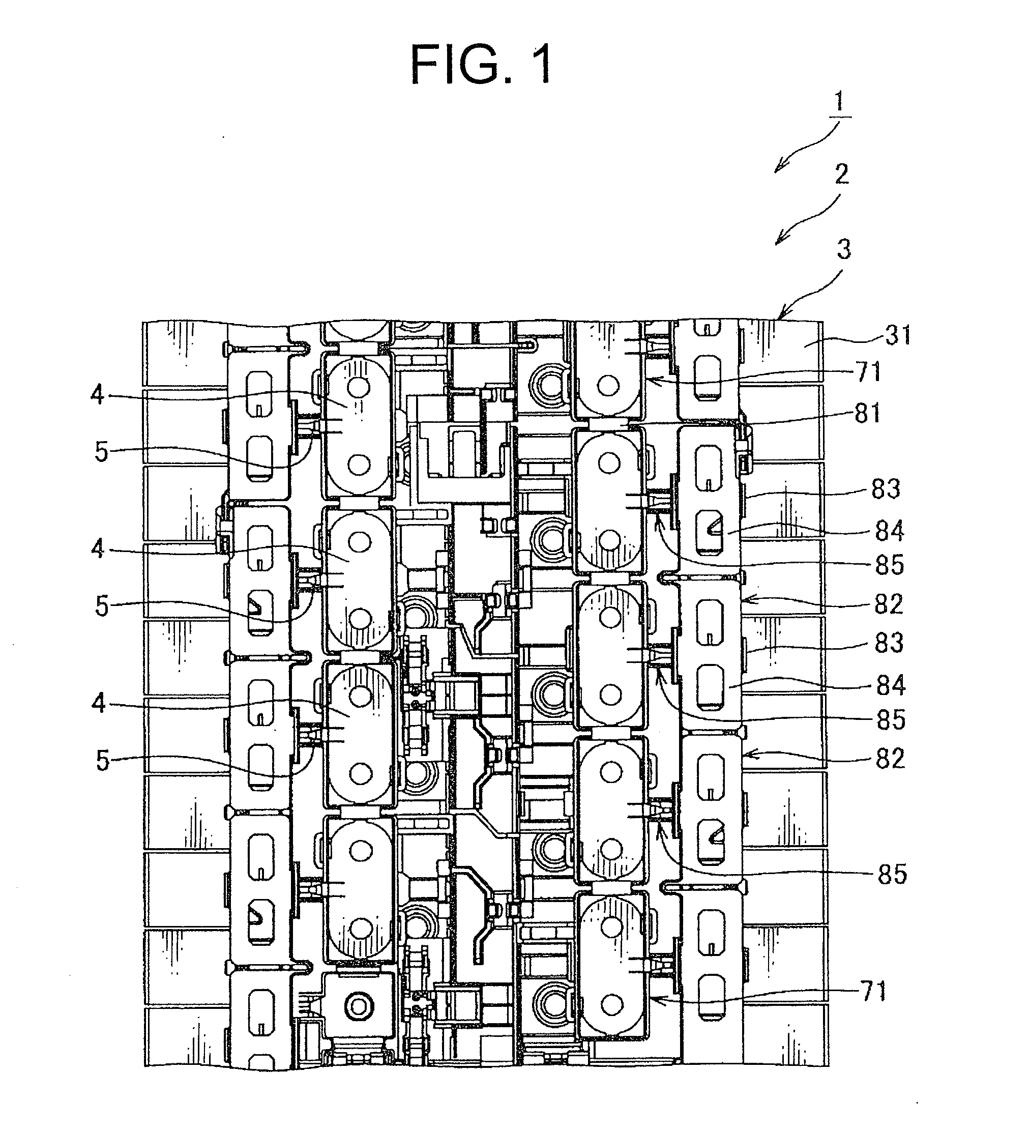
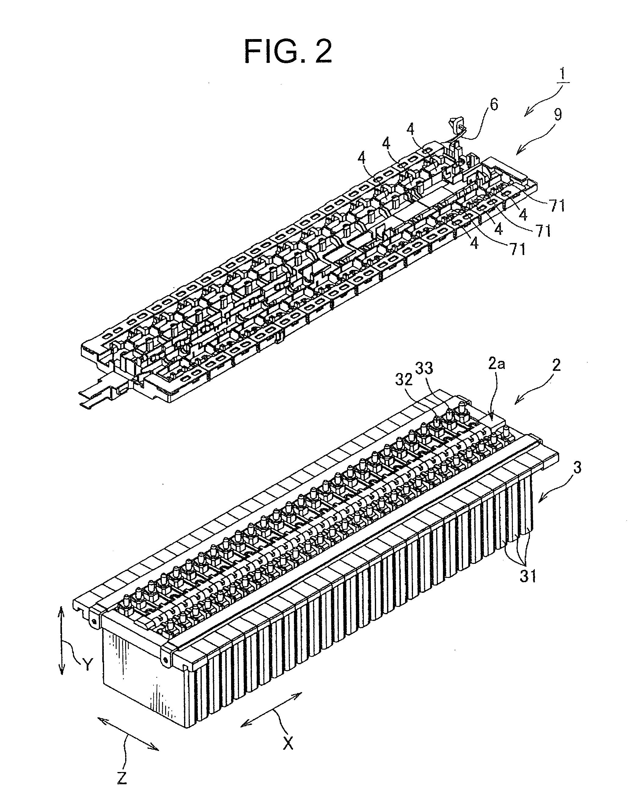
[0038]A power-supply device 1 according to the first embodiment of the present invention will be explained with reference to FIGS. 1 to 6. FIGS. 3 and 4 show a condition that a cover of a plate is removed. The power-supply device 1 is mounted on a hybrid vehicle which runs with a driving force of both an internal-combustion engine and an electric motor, and an electric vehicle which runs with the driving force of the electric motor.

[0039]The power-supply device 1 includes: a battery assembly 2 composed of a plurality of batteries 3 connected in series; a plurality of bus bars 4 connecting the batteries 3 in series by connecting electrodes 32, 33 of the batteries 3 adjacent to each other of the battery assembly 2; and a plurality of terminals 5 attached to each bus bar, and attached to an electric wire connected to a voltage measuring device for measuring a voltage of the battery; and a plate 9 for receiving these and overlapped with the battery assembly 2.

[0040]The battery assembly ...

second embodiment

[0068]The power-supply device 101 according to the second embodiment of the present invention will be explained with reference to FIGS. 7 and 8. The power-supply device 101 is mounted on a hybrid vehicle which runs with a driving force of both an internal-combustion engine and an electric motor, and an electric vehicle which runs with the driving force of the electric motor.

[0069]The power-supply device 101 includes: a battery assembly 2 composed of a plurality of batteries 3 connected in series; a plurality of bus bars 4 connecting the batteries 3 in series by connecting electrodes 32, 33 of the batteries 3 adjacent to each other of the battery assembly 2; and a plurality of terminals 105 attached to each bus bar, and attached to an electric wire connected to a voltage measuring device (not shown) for measuring a voltage of the battery; and a plate 9 for receiving these and overlapped with the battery assembly 2.

[0070]The terminal 105 is made by punching and folding a conductive me...

third embodiment

[0073]A power-supply device 201 according to the third embodiment of the present invention will be explained with reference to FIGS. 9 and 10. The power-supply device 201 is mounted on a hybrid vehicle which runs with a driving force of both an internal-combustion engine and an electric motor, and an electric vehicle which runs with the driving force of the electric motor.

[0074]The power-supply device 201 includes: a battery assembly 2 composed of a plurality of batteries 3 connected in series; a plurality of bus bars 4 connecting the batteries 3 in series by connecting electrodes 32, 33 of the batteries 3 adjacent to each other of the battery assembly 2; and a plurality of terminals 205 attached to each bus bar, and attached to an electric wire connected to a voltage measuring device (not shown) for measuring a voltage of the battery; and a plate 9 for receiving these and overlapped with the battery assembly 2.

[0075]The terminal 205 is made by punching and folding a conductive meta...


PUM

PropertyMeasurementUnit
polaritiesaaaaaaaaaa
voltageaaaaaaaaaa
electric potentialsaaaaaaaaaa

Abstract

The power-supply device includes: a battery assembly composed of a plurality of batteries each having a positive electrode at one end of the battery and a negative electrode at the other end of the battery, said batteries overlapped with each other in a manner that electrodes having the different polarities are adjacent to each other; a plurality of bus bars connecting the batteries in series by connecting the adjacent electrodes having the different polarities in the battery assembly; and a terminal having an electric contact part attached to each bus bar, and a wire connecting part continued to the electric contact part, and attached to an electric wire connected to a voltage measuring device for measuring a voltage of the battery. The electric contact part includes a pair of clipping pieces disposed with a gap from each other, and connected to the bus bar by press-inserting the bus bar into between the clipping pieces.

Description

CROSS REFERENCE TO RELATED APPLICATIONS[0001]This application is on the basis of Japanese Patent Application No. 2009-188949, the contents of which are hereby incorporated by reference.BACKGROUND OF THE INVENTION[0002]1. Field of the Invention[0003]The present invention relates to a power-supply device composed of a plurality of batteries connected in series, and mounted on a hybrid vehicle movable with both an internal-combustion engine and an electric motor drive, an electric vehicle, or the like.[0004]2. Description of the Related Art[0005]For example, a power-supply device 901 shown in FIG. 11 is mounted on a hybrid vehicle movable with both an internal-combustion engine and an electric motor drive, an electric vehicle, or the like. The power-supply device 901 includes: a plurality of batteries 903 in which different polarity electrodes 932, 933 are arranged adjacent to each other; a bus bar 904 for connecting the batteries 903 adjacent to each other; a terminal 905 for connecti...

Claims


Application Information

Patent Timeline
Patent Type & Authority Applications(United States)
IPC IPC(8): H01M10/48H01M50/503H01M50/529H01M50/505H01M50/51H01M50/517
CPCH01M2/206H01M2/307H01R13/113H01M10/482Y02E60/12H01M10/0413Y02E60/10H01M50/561Y02P70/50H01M50/517H01M50/51H01M50/505H01M50/503
Inventor IKEDA, TOMOHIROAOKI, KEIZO
Owner YAZAKI CORP
Why Eureka
Try Eureka