
Method for removing residual water from fuel cell

a fuel cell and residual water technology, applied in the direction of transportation fuel cell technology, transportation hydrogen technology, electrochemical generators, etc., can solve the problems of deteriorating the performance affecting the application of the fuel cell, and taking several hours to reach, so as to reduce maintain the water content in the membrane, and minimize the water content in the fuel cell

Active Publication Date: 2011-02-24
HYUNDAI MOTOR CO LTD +1
View PDF3 Cites 7 Cited by
  • Summary
  • Abstract
  • Description
  • Claims
  • Application Information

AI Technical Summary

Benefits of technology

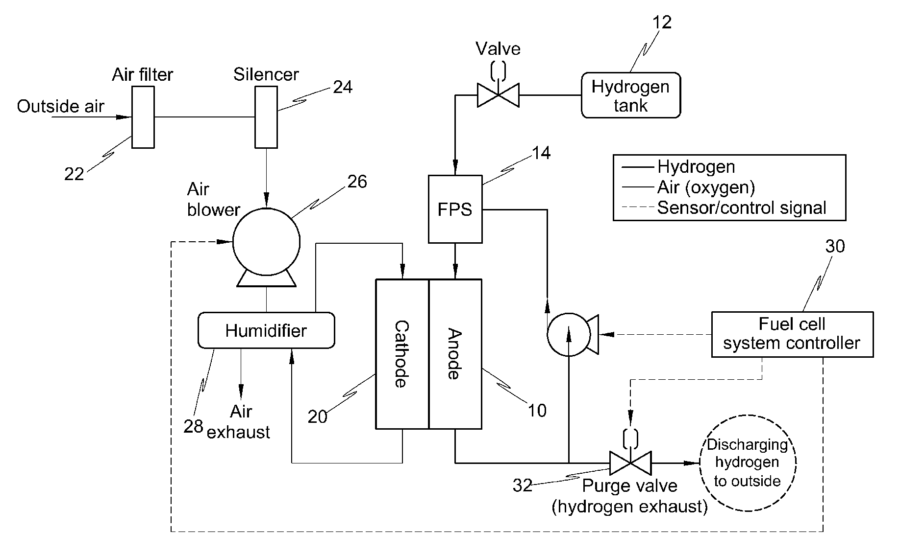
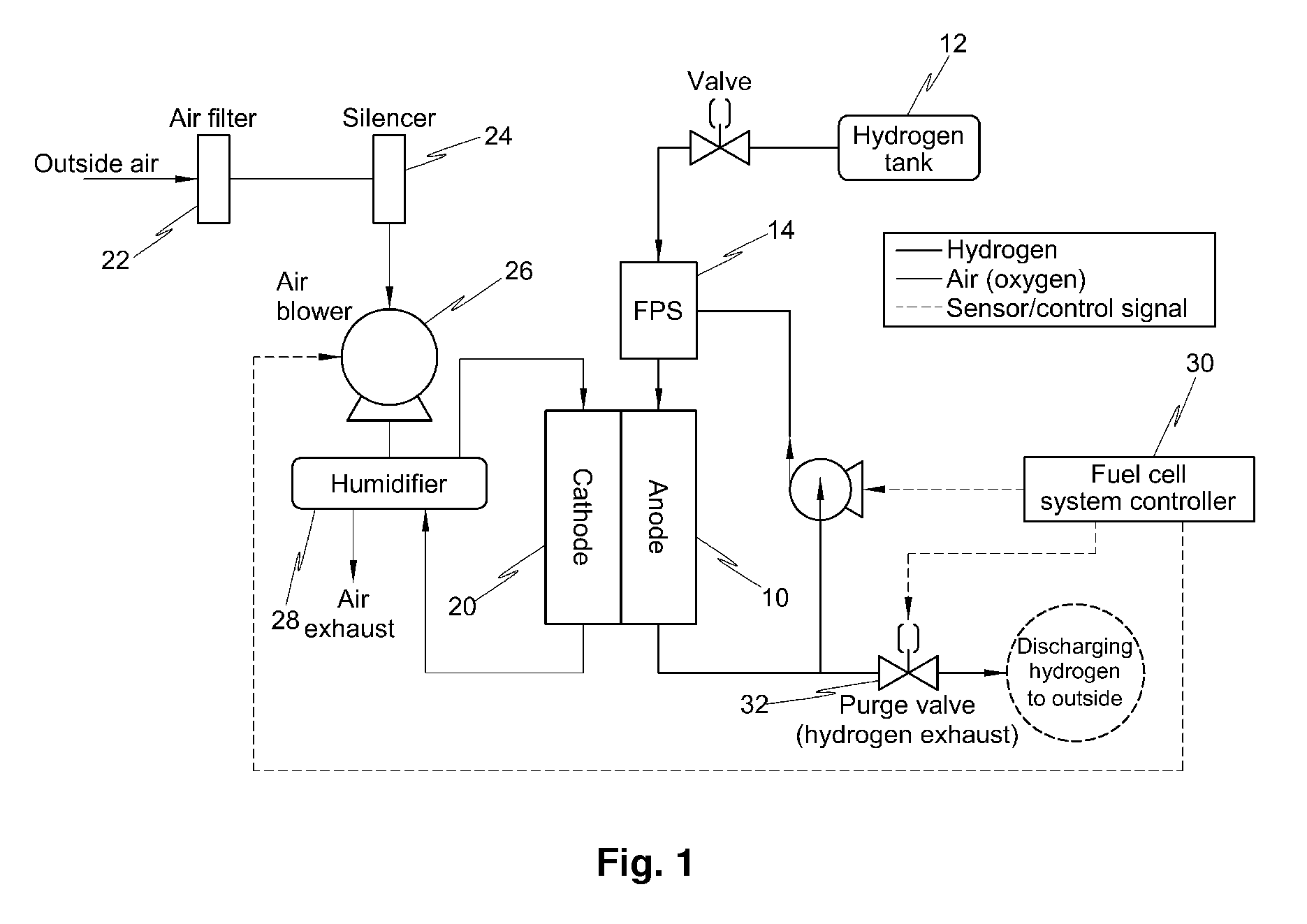
The present invention provides a method for reducing water content in a fuel cell by controlling the humidity of purge gases supplied to the anode and cathode. By selectively reducing water content in the fuel cell and membrane, the invention aims to improve the performance and durability of fuel cells in various vehicles. The invention can be applied during operation or after operation of the fuel cell. The technical effects of the invention include reducing water content in the fuel cell and membrane, maintaining high efficiency of the fuel cell, and improving durability of the fuel cell.

Problems solved by technology

Condensed water and impurities generated at each electrode reduce the active surface area of the catalyst layer to cause a loss to the reaction, thus deteriorating the performance of the fuel cell.
However, it takes several hours to reach the threshold value, and its applicability is not satisfactory.
In addition, U.S. Pat. No. 6,358,637 discloses a method for removing residual water in a fuel cell using a vacuum pump after a fuel cell system is shut down, which is effective in removing residual water using the vacuum pump when the temperature of the fuel cell is high; however, it requires a significant amount of energy to remove the water content in the fuel cell using the vacuum pump.
However, this method is still not satisfactory.
As discussed above, the prior art methods cannot effectively remove water from the fuel cell to maintain the humidity of the membrane.
That is, it may take a long time to remove water and additional power may be required to operate a blower or vacuum pump for removing the water.
Additionally, conventional purge methods result in dryout of the membrane, which is known to promote degradation of the membrane.

Method used


Image

  • Method for removing residual water from fuel cell
  • Method for removing residual water from fuel cell
  • Method for removing residual water from fuel cell

Examples


examples

[0056]The following examples illustrate the invention and are not intended to limit the same.

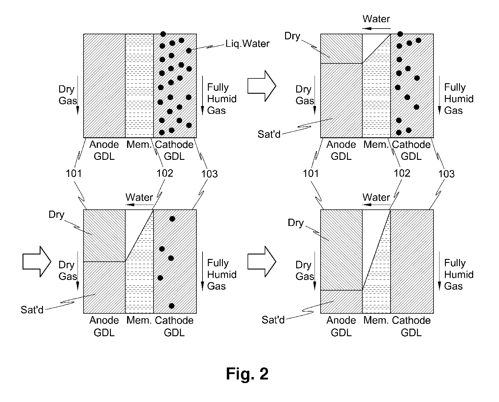
[0057]Purge gases were supplied to the anode and the cathode of a fuel cell having an active area of 250 cm2 by varying the relative humidities of purge gases to the anode and the cathode (i.e., 100% / 100%, 0% / 100%, 100% / 0%, and 50% / 50%, respectively) after operation with various flow rate and relative humidity of fuel gas at various current conditions. The change in water content of the fuel cell was investigated using neutron imaging and the change in ion conductivity of the membrane 102 was measured with a milliohm meter After operating the cell at each condition (which is the pre-purge condition), loads were turned off at each current level, and the flow rate of purge gases was maintained constant for 5 minutes (purging for 5 minutes).

[0058]1. In Case of Relative Humidities of 100% / 100% at the Anode and Cathode

[0059]FIG. 4 is a graph comparing the membrane resistance and the residual wate...


PUM

PropertyMeasurementUnit
areaaaaaaaaaaa
relative humiditiesaaaaaaaaaa
humidityaaaaaaaaaa

Abstract

The present invention provides a method for removing residual water in a fuel cell, which controls the humidity of purge gases to effectively remove residual water in the fuel cell and to maintain the humidity in a membrane at a constant level, thus ensuring the durability of the membrane.For this purpose, the present invention provides a method for removing residual water in a fuel cell, characterized in that the relative humidities of purge gases supplied to an anode and a cathode are controlled to selectively reduce water content in the fuel cell and water content in a membrane.

Description

BACKGROUND[0001](a) Technical Field[0002]The present disclosure relates to a method for removing residual water in a fuel cell, in which the humidity of purge gases is controlled to effectively remove residual water in the fuel cell and to maintain the humidity of the membrane at a nearly constant level, thus ensuring enhanced durability of the membrane.[0003](b) Background Art[0004]In general, a polymer electrolyte fuel cell (PEFC) comprises a fuel cell stack in which a plurality of unit cells are stacked. In each unit cell, an anode and a cathode are disposed on both sides of an electrolyte membrane to form a membrane electrode assembly (MEA), and the MEA is disposed between separators (bipolar plates).[0005]In the fuel cell, hydrogen as fuel is supplied to the anode (“fuel electrode”) and oxygen in air is supplied to the cathode (“air electrode” or “oxygen electrode”).[0006]The hydrogen supplied to the anode is dissociated into hydrogen ions and electrons by a catalyst disposed i...

Claims


Application Information

Patent Timeline
Patent Type & Authority Applications(United States)
IPC IPC(8): H01M8/04
CPCH01M8/04141H01M8/04179H01M8/045H01M8/04507H01M8/04514Y02E60/50H01M8/04835H01M2008/1095H01M2250/20Y02T90/32H01M8/04522Y02T90/40
Inventor CHO, KYU TAEKYOON, JONG JINLEE, JONG HYUNMENCH, MATTHEW M.TURHAN, AHMET
Owner HYUNDAI MOTOR CO LTD
Learn More