Fabrication of conductive pathways, microcircuits and microstructures in microfluidic networks

a technology of microfluidic networks and conductive pathways, which is applied in the direction of microstructural devices, microstructures, microstructures, etc., can solve the problems of undesirable shrinkage of molded metal, difficult to combine and integrate into a single device,

Active Publication Date: 2011-02-24
PRESIDENT & FELLOWS OF HARVARD COLLEGE
View PDF37 Cites 66 Cited by
  • Summary
  • Abstract
  • Description
  • Claims
  • Application Information

AI Technical Summary

Benefits of technology

[0033]Other advantages and novel features of the present invention will become apparent from the following detailed description of various non-limiting embodiments of the invention when considered in conjunction with the accompanying figures. All references cited herein, whether patents, patent applications, or technical literature publications are incorporated herein by ref

Problems solved by technology

In conventional devices, the microfluidic components and the electrically conductive pathways and components are separate structures, which can be difficult to combine and integrate together into a single device.
However, LIGA and other conventional injection molding tec

Method used


Image

  • Fabrication of conductive pathways, microcircuits and microstructures in microfluidic networks
  • Fabrication of conductive pathways, microcircuits and microstructures in microfluidic networks
  • Fabrication of conductive pathways, microcircuits and microstructures in microfluidic networks

Examples


example 1

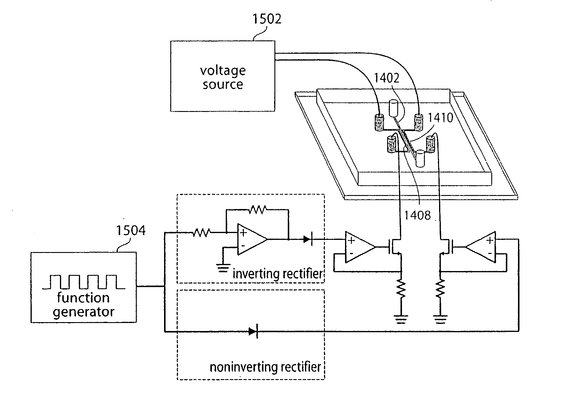
Fabrication of an LED Device Using a PDMS Microfluidic Structure

[0160]A structure comprising a first and a second microfluidic channel, not in electrical connection with each other, was fabricated using PDMS. The channels were filled with a 0.01 mM solution of octadecanethiol (HS(CH2)17CH3); the solution was then removed from the channels, which resulted in a layer of octadecanethiol deposited on the walls of the channel. This layer of octadecanethiol enabled the walls of the channel to be wetted by a liquid metal in a later step. An LED was placed between the outlets of the two channels such that the terminals of the LED bridged the two channels. The channels were then filled with a clean low-melting solder alloy (e.g., LMA-117; the solder was unoxidized and kept under water at pH 1 prior to use). Once inside the channel, the solder was manipulated from the outside by melting it with a warm soldering iron. The solder was moved and redirected in the channel using the soldering iron....

example 2

Improving Liquid Metal (Solder) Wetting of PDMS Microfluidic Channels Using an Alkanethiol

[0162]This example shows the degree to which a liquid metal (e.g., low-melting solder) wets different walls of a channel depending on the material in which the channel is made and / or the chemical that is patterned on the walls of the channel. Contact angles (in degrees) of 10 microliter (μL) drops of low-melting solder alloy LMA-117 (Small Parts, Inc.) on dry PDMS and glass were measured after washing the surfaces with 10 mM octadecanethiol in ethanol. Each contact angle was measured twice: once immediately after placing the drop on the surface, and again after re-melting the drop briefly (˜70 degrees Celsius, 1 minute) and allowing it to return to room temperature.

TABLE 1Contact angles (degrees) of low-melting solder alloy LMA-117on glass and dry PDMSGlass (clean)PDMSThiolFreshReheatFreshReheatnone145139133123Hexadecanethiol1401311191191-mercapto-undecanoic acid1401359088

example 3

Techniques Used for Fabrication of Conducting Pathways in Microfluidic Structures

[0163]Making Microfluidic Channels in PDMS and Filling Channels with Solder to Form “Microsolidic Structures”

[0164]Microsolidic structures were fabricated according to the procedure illustrated in FIG. 5. In Step A, masters 500 of the lower and upper layers of a network of microfluidic channels were fabricated in SU-8 photoresist (MicroChem, Inc.) 502 on silicon wafers 501 (in bas-relief) using a procedure described previously in U.S. Pat. No. 6,645,432 and in Xia, Y.; Whitesides, G. M. Soft Lithography. Angew. Chem. Intl. Ed. 1998, 37, 550-575; and Duffy, D. C.; McDonald, J. C.; Schueller, O. J. A.; Whitesides, G. M. Rapid Prototyping of Microfluidic Systems in Poly(dimethylsiloxane). Anal. Chem. 1998, 70, 4974-4984. The wafers were silanized with (tridecafluoro-1,1,2,2-tetrahydrooctyl)-1-trichlorosilane overnight. In Step B, freshly prepared PDMS (Sylgard 184, Dow Corning, Inc) was spin-coated on the ...


PUM

PropertyMeasurementUnit
Temperatureaaaaaaaaaa
Lengthaaaaaaaaaa
Lengthaaaaaaaaaa

Abstract

Disclosed herein are a variety of microfluidic devices and solid, typically electrically conductive devices that can be formed using such devices as molds. In certain embodiments, the devices that are formed comprise conductive pathways formed by solidifying a liquid metal present in one or more microfluidic channels (such devices hereinafter referred to as “microsolidic” devices). In certain such devices, in which electrical connections can be formed and/or reformed between regions in a microfluidic structure; in some cases, the devices/circuits formed may be flexible and/or involve flexible electrical components. In certain embodiments, the solid metal wires/conductive pathways formed in microfluidic channel(s) may remain contained within the microfluidic structure. In certain such embodiments, the conductive pathways formed may be located in proximity to other microfluidic channel(s) of the structure that carry flowing fluid, such that the conductive pathway can create energy (e.g. electromagnetic and/or thermal energy) that interacts withy and/or affects the flowing fluid and/or a component contained therein or carried thereby. In other embodiments, a microsolidic structure may be removed from a microfluidic mold to form a stand-alone structure. In certain embodiments, the solid metal structures formed may interact with light energy incident upon a structure or may be used to fabricate a light-weight electrode. Another aspect of the invention relates to the formation of self-assembled structures that may comprise these electrically conductive pathways/connections.

Description

FEDERALLY SPONSORED RESEARCH[0001]Various aspects of the presented invention were sponsored by the National Institutes of Health (NIH) (Grant nos. GM065364 and GM067445), DARPA, the Office of Naval Research and the National Science Foundation (Grant no. MLR-0213805). The Government may have certain rights in the invention.FIELD OF INVENTION[0002]One aspect of this invention generally relates to devices in which conductive pathways and electrical connections / circuits can be formed and / or reformed in a structure, particularly a microfluidic structure. In some cases, the devices involve flexible electrical circuits and / or components.BACKGROUND[0003]There are many uses for systems that cause fluid to flow through channels, including microfluidic channels, i.e., channels having at least one dimension in the micron range (less than one millimeter). For instance, there are many examples of systems for analyzing very small amounts of samples and reagents on chemical “chips” that include ver...

Claims


Application Information

Patent Timeline
IPC IPC(8): C12M1/00G01N33/00H01R43/00
CPCB01L3/5027Y10T29/49117B01L2200/12B01L2300/0645B01L2300/0816B01L2300/0874B01L2400/0415H05K1/0272H05K1/032H05K3/101H05K3/389H05K2201/0162H05K2201/0305H05K2203/128B01L3/502707B33Y80/00B81B7/00B01F33/00
Inventor BRUZEWICZ, DEREK A.BONCHEVA-BETTEX, MILAWHITESIDES, GEORGE M.SIEGEL, ADAMWEIBEL, DOUGLAS B.SHEVKOPLYAS, SERGEY S.MARTINEZ, ANDRES
Owner PRESIDENT & FELLOWS OF HARVARD COLLEGE
Why Eureka
Try Eureka