Water stop structure for wire harness and method of forming water stop section

a technology of water stop and wire harness, which is applied in the direction of insulated conductors, cable connections, coupling devices, etc., can solve the problem of becoming more difficult to insert the terminals into the terminal accommodating chamber, and achieve the effect of easy formation

Inactive Publication Date: 2011-02-24
SUMITOMO WIRING SYST LTD
View PDF32 Cites 20 Cited by
  • Summary
  • Abstract
  • Description
  • Claims
  • Application Information

AI Technical Summary

Benefits of technology

[0015]As described above, in the present invention, the water stop section is provided by applying a water stop treatment to the core of the wire at the position closest possible to the connector at a side of the wires connected to the connector of the electronic control unit. Since the water stop section is formed by filling the waterproofing agent into clearances between the strands of the core exposed part and coating the core exposed part with the waterproof sheet, water between strands can be blocked by the water stop section even if water penetrates between the strands due to a damage of an insulation coating. Therefore, even if the connector connected with the electronic control unit is a non-waterproof connector, water penetration into the electronic control unit from the wire side can be prevented.
[0021]If the water stop section is provided at the leading end side of the wire bundled part in this way, the terminals at the ends of the respective wires can be smoothly inserted and locked in the terminal accommodating chambers of the connector. In addition, since no external interfering member is present in the range of about 10 mm to 100 mm very close to the connector, there is no likelihood of damaging the insulation coatings of the wires and a water stop treatment is applied at this position, whereby water having penetrated to the cores can be reliably blocked to prevent water penetration into the electronic control unit.
[0023]If not only the waterproofing agent is dropped to the core exposed part, but also the crimping terminal is swaged and crimped to the core in this way, clearances between the strands can be eliminated. Thus, by applying the water stop treatment in two steps by swaging and crimping by the crimping terminal and filling of the waterproofing agent, water penetrating through the clearances between the strands can be more reliably blocked.
[0027]Since the above electronic control unit relates to a running safety system of the automotive vehicle, it needs to be prevented that water penetrates from the connector connecting portion with the wire harness to cause a malfunction in the control of the electronic control unit. Thus, reliability in running safety can be improved by providing the water stop section at the wire side immediately before the connector connecting portion and reliably preventing water penetration to the electronic control unit.
[0032]In the method of forming the water stop section according to the present invention, after the core is exposed from the insulation coating at a position close to a terminal crimping portion for connector connection, the waterproofing agent is dropped and, then, the wire is set in a pressurized container, into which pressure air is supplied. By loading the part of the wire, to which the waterproofing agent was dropped, with pressure air in this way, the waterproofing agent can be reliably pressed into the clearances between the strands of the core exposed part. In addition, the waterproofing agent can be pressed into the clearances between the strands of the core inside the parts of the insulation coating at the opposite sides of the core exposed part and into the clearances between the parts of the inner surface of the insulation coating and the strands. Therefore, the water stop section of the wire can be relatively easily formed immediately before the connector connecting portion with the electronic control unit.
[0033]As described above, the water stop section is provided by applying the water stop treatment to the core of the wire at the position closest possible to the connector in the wire harness having the end thereof connected with the connector connected with the electronic control unit. Thus, if water penetrates into the clearances between the stands due to a damage of the insulation coating at a position of the wire side distant from the water stop section, water can be blocked immediately before the connector connecting portion. Therefore, even if the connector connected to the electronic control unit is a non-waterproof connector, water penetration from the wire side to the electronic control unit can be prevented.

Problems solved by technology

If a water stop section coated with a waterproof sheet is provided at this wire loosened position, intervals between the terminal accommodating chambers of the connector become larger than those between the wires due to an increase in a wire diameter and it becomes more difficult to insert the terminals into the terminal accommodating chambers.

Method used


Image

  • Water stop structure for wire harness and method of forming water stop section
  • Water stop structure for wire harness and method of forming water stop section
  • Water stop structure for wire harness and method of forming water stop section

Examples


first embodiment

[0044]FIGS. 1 to 6 show a

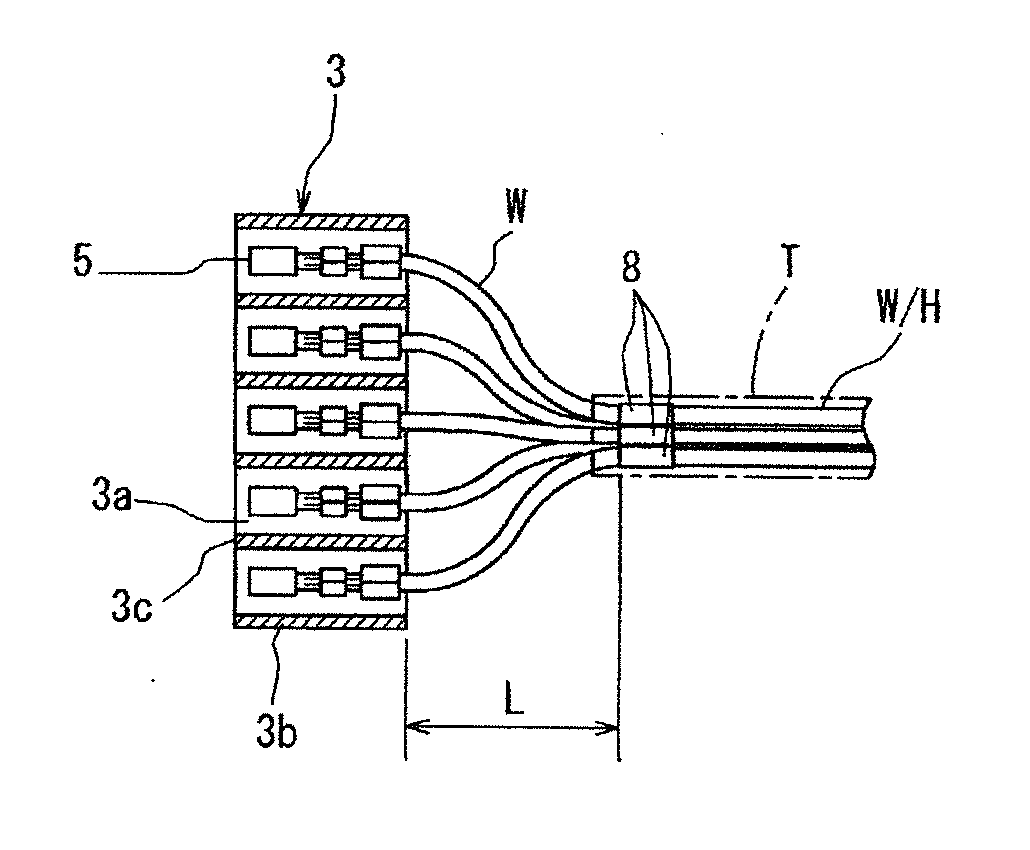
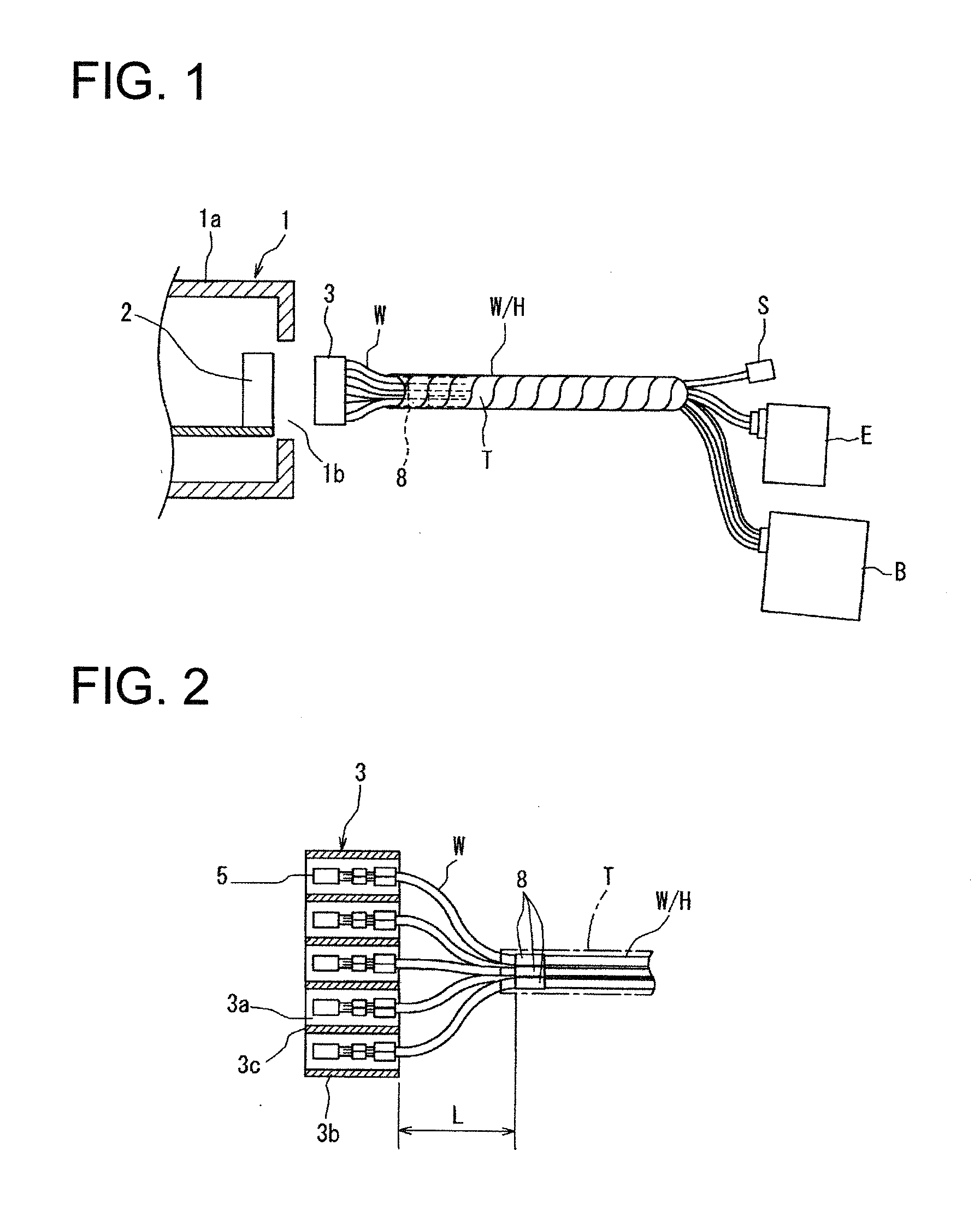
[0045]As shown in FIG. 1, a connector 3 is connected to a leading end of a wire harness W / H of this embodiment. This connector 3 is mated with a connector 2 mounted on a circuit board of an electronic control unit 1 (hereinafter, called “ECU”) installed in an engine compartment of an automotive vehicle and is a unit connecting connector.

[0046]The electronic control unit 1 is installed in a water-free area not subject to water. Hence, a connecting portion between the connector 2 of the electronic control unit 1 and the connector 3 at the end of the wire harness is not subject to water.

[0047]The ECU 1 of this embodiment is an engine fuel control unit. Wires of the wire harness W / H connector-connected to the ECU 1 are connected to sensors S such as an O2 sensor, a speed sensor, a knock sensor and a collision sensor, another electronic control unit E and a fuse, a relay and a connector of an electrical connection box B.

[0048]A plurality of wires W are bundled by...

second embodiment

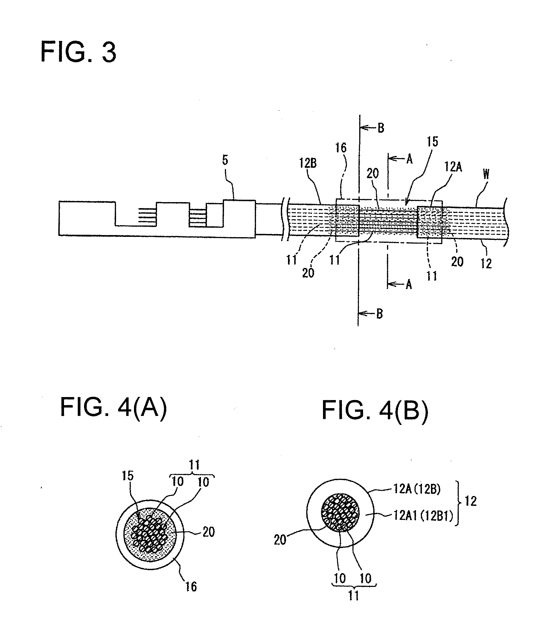
[0078]In a first modification of the second embodiment shown in FIG. 7(B), there is used a crimping terminal 32 in which a barrel portion 32a to be crimped and connected to the insulation coating 12B is connected to an intermediate barrel portion 32c via a base plate portion 32b. The other construction is same as in a second modification.

[0079]In the second modification shown in FIG. 7(C), there is used a crimping terminal 35 in which barrel portions 35a, 35b to be swaged and crimped to the insulation coatings 12A, 12B at the opposite sides of the core exposed part 15 and an intermediate barrel portion 35c to be swaged and crimped to the core of the core exposed part 15 are connected via a base plate portion 35d. The other construction is same as in the first modification.

[0080]If not only the waterproofing agent 20 is dropped to the core exposed part 15, but also the crimping terminal is swaged and crimped to the core 11 as in the second embodiment, the clearances between the stran...

third embodiment

[0081]FIG. 8 shows a

[0082]Although the waterproof sheet 16 is wound around the water stop section 8 in the first embodiment, the water stop section 8 is coated with a heat shrinkable tube 40 having an adhesive 41 applied to an inner surface thereof instead of with the waterproof sheet. In other words, after being mounted on the water stop section 8, the heat shrinkable tube 40 is heated to be shrunk and is fixed to the outer circumferential surface of the water stop section 8 and those of the insulation coatings 12A, 12B at the opposite sides by the adhesive 41.

[0083]The other construction is similar to the first embodiment and functions and effects are also similar.

[0084]Although the ECU 1 is an engine fuel control unit in the first embodiment, the present invention is suitably used also in the case where a wire harness is connector-connected to an engine control unit, an ABS control unit, an airbag control unit, a running safety control unit, a vehicle radar control unit or a nigh...


PUM


Abstract

A water stop structure is provided for a wire harness connected to an electronic control unit installed in an automotive vehicle or a motorcycle. Terminals mounted on ends of wires constituting the wire harness are inserted and locked for connection in a unit connecting connector to be mated with a connector of the electronic control unit, each wire connected to the unit connecting connector includes a water stop section at a position very close to the connector, and the water stop section is formed by filling a waterproofing agent into clearances between strands of a core exposed part formed by removing an insulation coating covering the core of each wire and coating the core exposed part with a waterproof member.

Description

BACKGROUND OF THE INVENTION[0001]1. Field of the Invention[0002]The present invention relates to a water stop structure and a method of forming a water stop section and is particularly designed to prevent water penetration into an electronic control unit from wires of a wire harness via a connector connecting portion in the wire harness connected a connector of the electronic control circuit.[0003]2. Description of the Related Art[0004]In the case of arranging a wire harness along a water susceptible area in a vehicle such as an automotive vehicle or a motorcycle, a connector connecting portion between the wire harness and an electronic control circuit installed in the vehicle needs to be so designed as to prevent water penetration from wires of the wire harness to the electronic control circuit.[0005]At this time, even if an arrangement path of the wire harness is set in an area not subject to water, water might penetrate to the wires from a water-stop treated portion to the connec...

Claims


Application Information

Patent Timeline
Patent Type & Authority Applications(United States)
IPC IPC(8): H01R13/52B05D5/12
CPCB60R16/0207H02G15/046H02G3/088H01B7/2825
Inventor SAWAMURA, NAOHITO
Owner SUMITOMO WIRING SYST LTD
Why Eureka
Try Eureka