Manufacturing system including modular assembly station for flexible manufacturing and optional automated component part feed system therefor

Inactive Publication Date: 2011-03-03
DURR ECOCLEAN INC
View PDF27 Cites 21 Cited by
  • Summary
  • Abstract
  • Description
  • Claims
  • Application Information

AI Technical Summary

Benefits of technology

[0014]The automated component part feed system solves problems associated with prior feed systems for supplying manufacturing operations with component parts, by making it possible to process a plurality of different component parts utilizing one hopper, one conveyor and one component part robotic manipulator without having to duplicate the hoppers/conveyors/robotic manipulators for each of

Problems solved by technology

Modern manufacturing has required ever-increasing complexity due to the desire to manufacture multiple products on a single assembly line.
It has proven increasingly difficult to produce, for example, both V-6 and V-8 engine cylinder heads or cylinder blocks, on a single assembly line.
This has proven cost prohibitive and driven up the cost to manufacture these types of products.
A particular problem is related to the variation of production volumes between different products to be manufactured.
It is cost prohibitive to prepare an entire line that will be left idle during that period due to the capital intensive requirements associated with preparing a designated manufacturing line.
Additionally, when one product is phased out and another instituted, an

Method used


Image

  • Manufacturing system including modular assembly station for flexible manufacturing and optional automated component part feed system therefor
  • Manufacturing system including modular assembly station for flexible manufacturing and optional automated component part feed system therefor
  • Manufacturing system including modular assembly station for flexible manufacturing and optional automated component part feed system therefor

Examples


Example

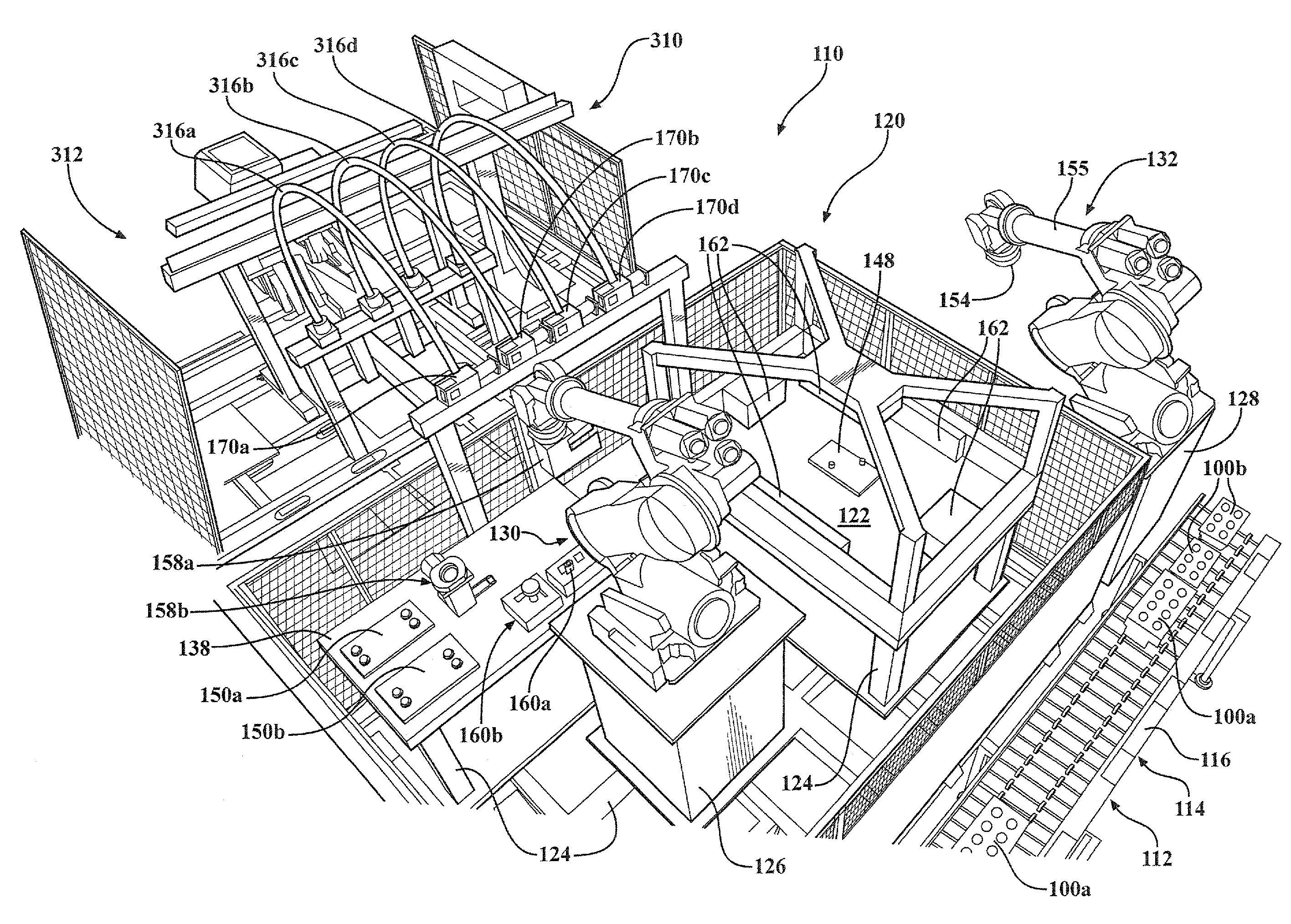
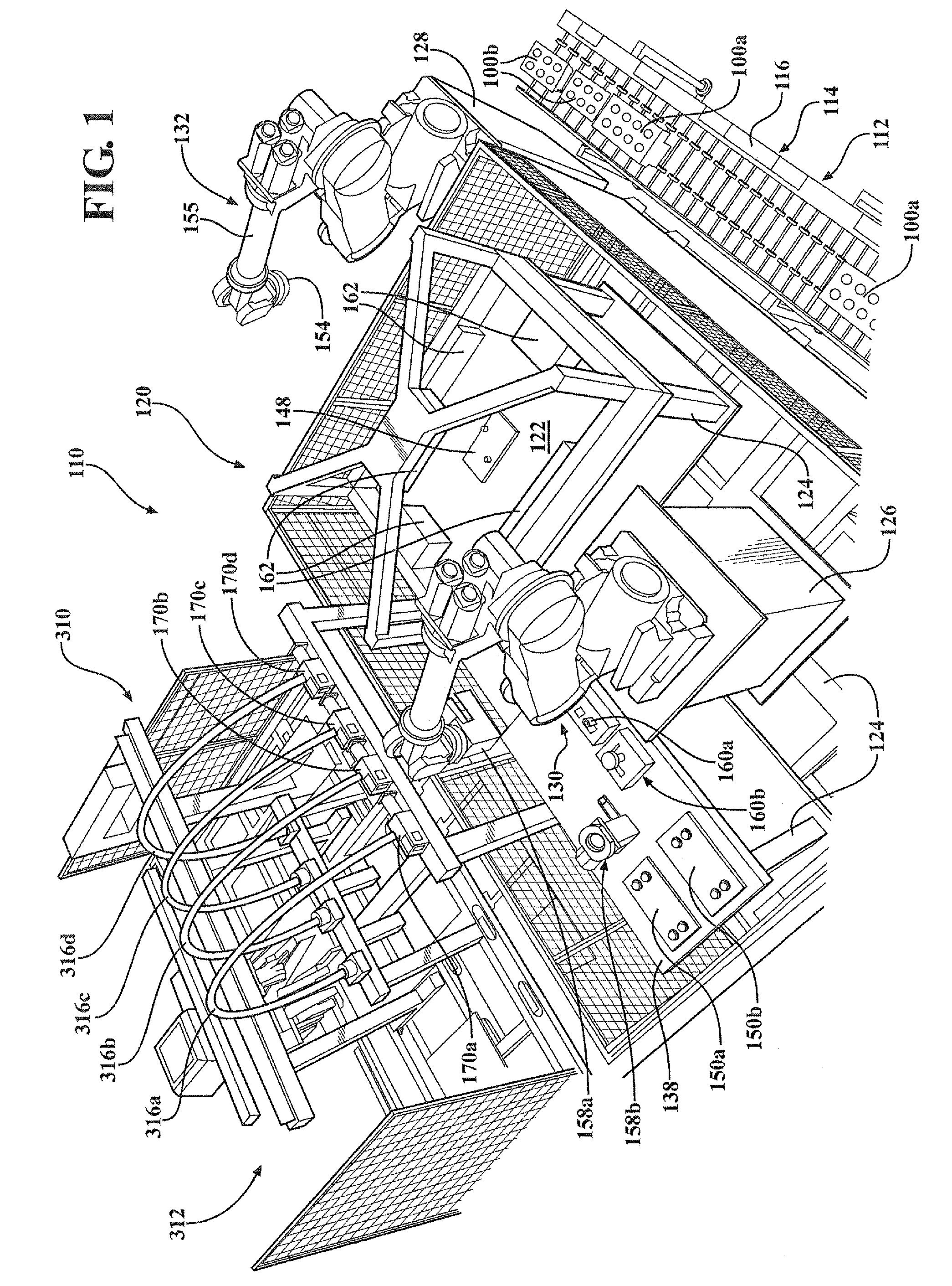
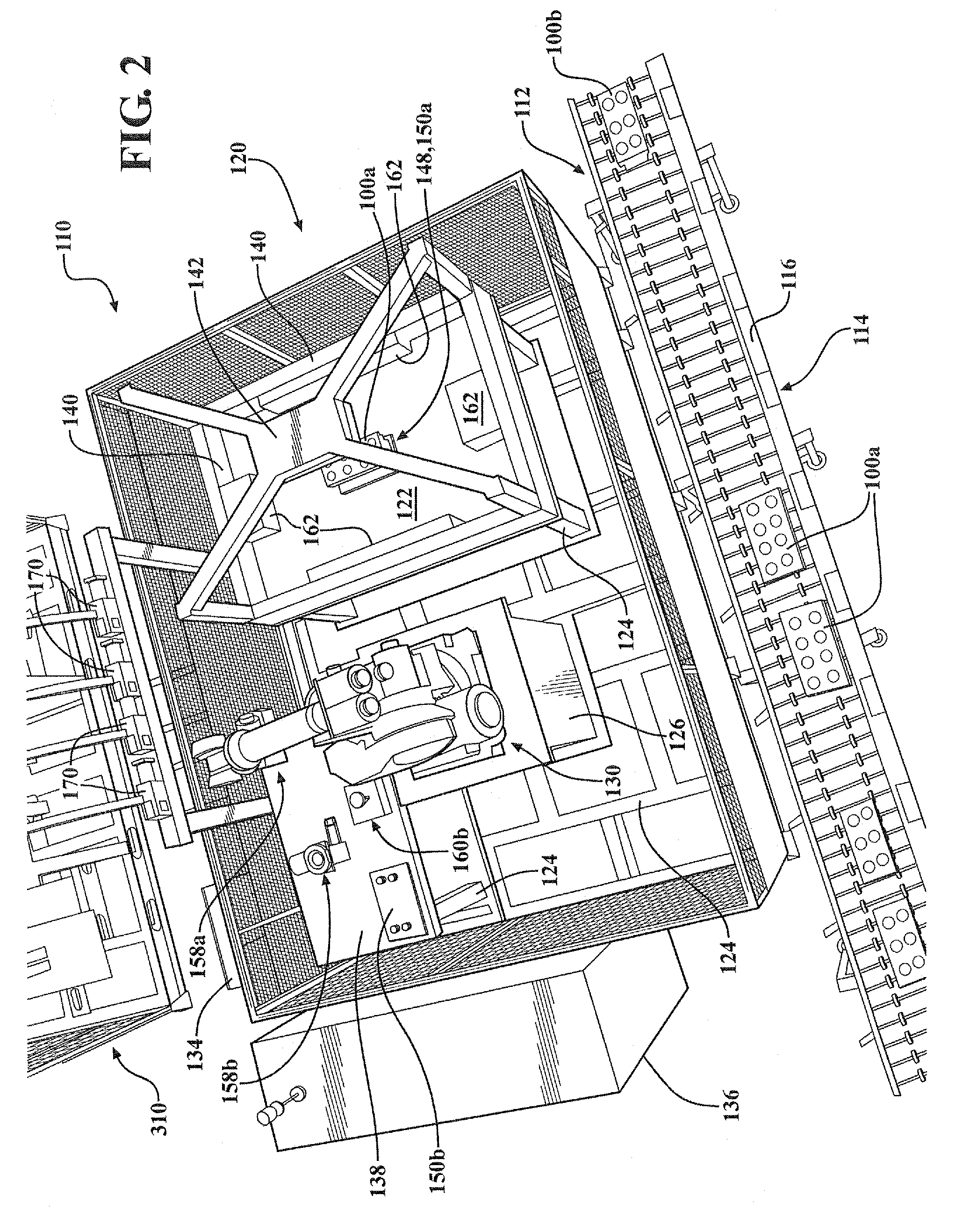
[0049]Referring to FIGS. 1-3 and 11-16, first embodiment modular assembly station or apparatus 120 of manufacturing system 110 is shown.

[0050]Modular assembly station 120 includes work surface 122 mounted upon frame 124. First and optional second manipulator platforms 126, 128 are disposed on opposite sides of and adjacent to the work surface 122. Platform 126 is also mounted to the frame 124. Optional second platform 128 may be located outside of the work cell in which work surface 122 and first manipulator platform 126 are contained, but is considered adjacent to work surface 122 with which may interact.

[0051]A first robotic manipulator 130 is mounted upon the first manipulator platform 126 and an optional second robotic manipulator 132 is mounted upon the second manipulator platform 128. Although it is contemplated that robotic manipulator 130 may carry out all robotic manufacturing operations on workpieces 100, optional second robotic manipulator 132 may be particularly useful f...

Example

[0060]Referring to FIGS. 4-10, alternative second embodiment modular assembly station or apparatus 220 of manufacturing system 110 is shown. Modular assembly station 220 includes work surface 222 mounted upon frame 224. First and second manipulator platforms 226, 228 are disposed on opposite sides of and adjacent to the work surface 222. Each of the platforms 226, 228 is also mounted to the frame 224.

[0061]A first robotic manipulator 230 is mounted upon the first manipulator platform 226 and a second robotic manipulator 232 is mounted upon the second manipulator platform 228. Although it is contemplated that each robotic manipulator 230, 232 may have a designated task in carrying out the manufacturing operations on workpieces 100a, 100b, it is preferred that the robotic manipulators 230, 232 each be able to perform some if not all of the robotic manufacturing operations within assembly station 220. Robotic manipulators 230, 232 are controlled by controller 234 and electronics panel ...


PUM

PropertyMeasurementUnit
Pressureaaaaaaaaaa
Flexibilityaaaaaaaaaa

Abstract

A manufacturing system including an apparatus in which a plurality differently configured workpieces requiring manufacturing operations are processed. The apparatus includes a work surface configured to receive apparatus components and a plurality of differently configured workpieces, a tool table adjacent the work surface providing support for tooling and apparatus components required to process various manufacturing operations on the workpieces, and a robotic manipulator positioned adjacent to the work surface and the tool table and having a gripping device configured to grip at least one of the apparatus components. Also, an automated feed system optionally included in the system for supplying component parts to the manufacturing operation. Also, a method of assembling first and second differently configured workpieces.

Description

CROSS-REFERENCE TO RELATED APPLICATIONS[0001]This application claims priority to U.S. Provisional Applications Nos. 61 / 226,917 filed Jul. 20, 2009, and 61 / 278,849 filed Oct. 13, 2009, the complete disclosures of which are both incorporated herein by reference.BACKGROUND OF THE INVENTION[0002]a. Field of the Invention[0003]The invention relates to the field of modular manufacturing systems, and automated feed systems for supplying component parts thereto.[0004]b. Description of the Related Art[0005]Modern manufacturing has required ever-increasing complexity due to the desire to manufacture multiple products on a single assembly line. It has proven increasingly difficult to produce, for example, both V-6 and V-8 engine cylinder heads or cylinder blocks, on a single assembly line. Therefore, manufacturers of these types of products have been required to design and manufacture duplicate assembly lines, for example, one for a V-6 engine cylinder head or cylinder block, and another for a...

Claims


Application Information

Patent Timeline
IPC IPC(8): B23P19/00
CPCB23P21/00Y10T29/53Y10T29/5313B25J9/0084
Inventor IMMEKUS, WILLIAM J.JACKSON, MARK
Owner DURR ECOCLEAN INC
Why Eureka
Try Eureka