Vibration element coupled with non-linear force to improve non-resonant frequency response

a non-linear force and vibration element technology, applied in the field of energy harvesting and vibration sensing, can solve the problems of small amount of available power being scavenged, unable to achieve the improvement of scavenging efficiency, and many naturally occurring vibration sources do not have a fixed frequency of vibration, so as to achieve efficient scavenging energy and improve the overall non-resonant response of vibration elements.

Inactive Publication Date: 2011-03-03
UNIV OF LOUISVILLE RES FOUND INC
View PDF18 Cites 44 Cited by
  • Summary
  • Abstract
  • Description
  • Claims
  • Application Information

AI Technical Summary

Benefits of technology

[0010]Embodiments of the invention address these and other problems associated with the prior art by coupling a non-linear force to a vibration element such as a piezoelectric cantilever to introduce non-linear dynamics such as chaotic (i.e., non-resonant), sub-harmonic, and amplifying vibration in the vibration element and thereby ...

Problems solved by technology

However, many naturally occurring vibration sources do not have a fixed frequency of vibration, and vibrate over a broad spectrum of frequencies.
Lack of coupling of the piezoelectric cantilever to the off-resonance vibrations means that only a small amount of the available power can be scavenged.
It is expected, however, that the power consumed by active tuning would completely offset any improvement obtained in the scavenging ...

Method used


Image

  • Vibration element coupled with non-linear force to improve non-resonant frequency response
  • Vibration element coupled with non-linear force to improve non-resonant frequency response
  • Vibration element coupled with non-linear force to improve non-resonant frequency response

Examples


working example 1

Single and Double Cantilevers

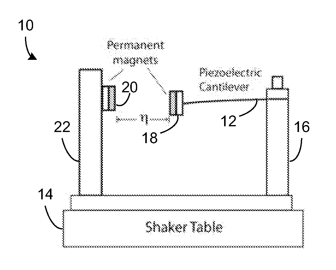
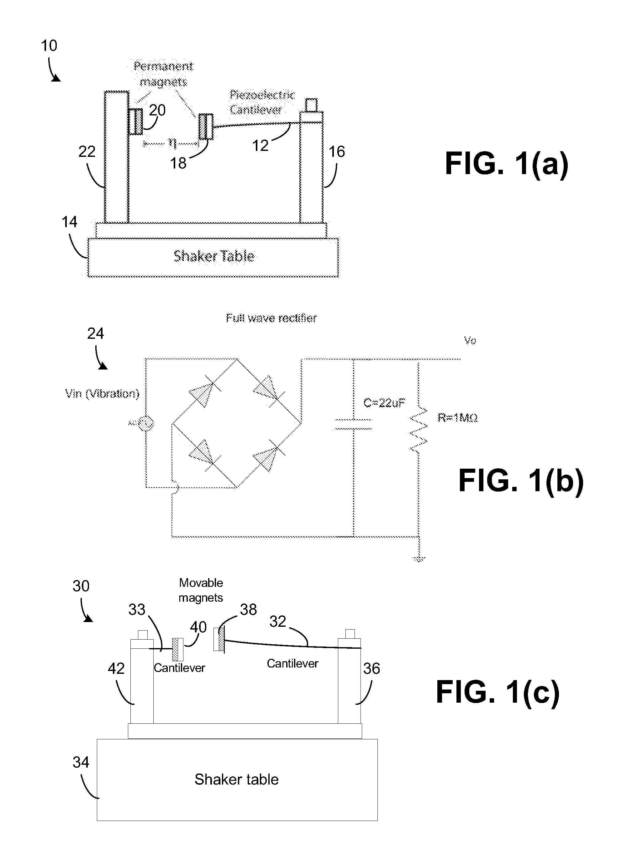
[0061]A test set up configured in the manner illustrated above in connection with FIGS. 1(a) and 1(b) was constructed. Cantilever 12 was manufactured using commercially available unimorph piezoelectric discs composed of an about 0.09 mm thick PZT layer deposited on an about 0.1 mm thick brass shim (APC International, MFT-50T-1.9A1). The disc was cut into an about 13 mm wide by about 50 mm long strip, and clamped at one end to produce an about 44 mm long cantilever. The PZT layer extended about 25 mm along the length of the cantilever, and the remainder was composed only of brass. The proof mass (including the magnet and an additional fixture that holds the magnet) weighed about 2.4 gm, while the cantilever itself weighed about 0.8 gm. The electrical leads were soldered with thin lead wires (134 AWP, Vishay) to the top side of the PZT and the bottom side of the shim.

[0062]Vibration was generated by a shaker table 14 (Labwork ET-126) powered by an amplifie...

working example 2

Pink Noise Vibration

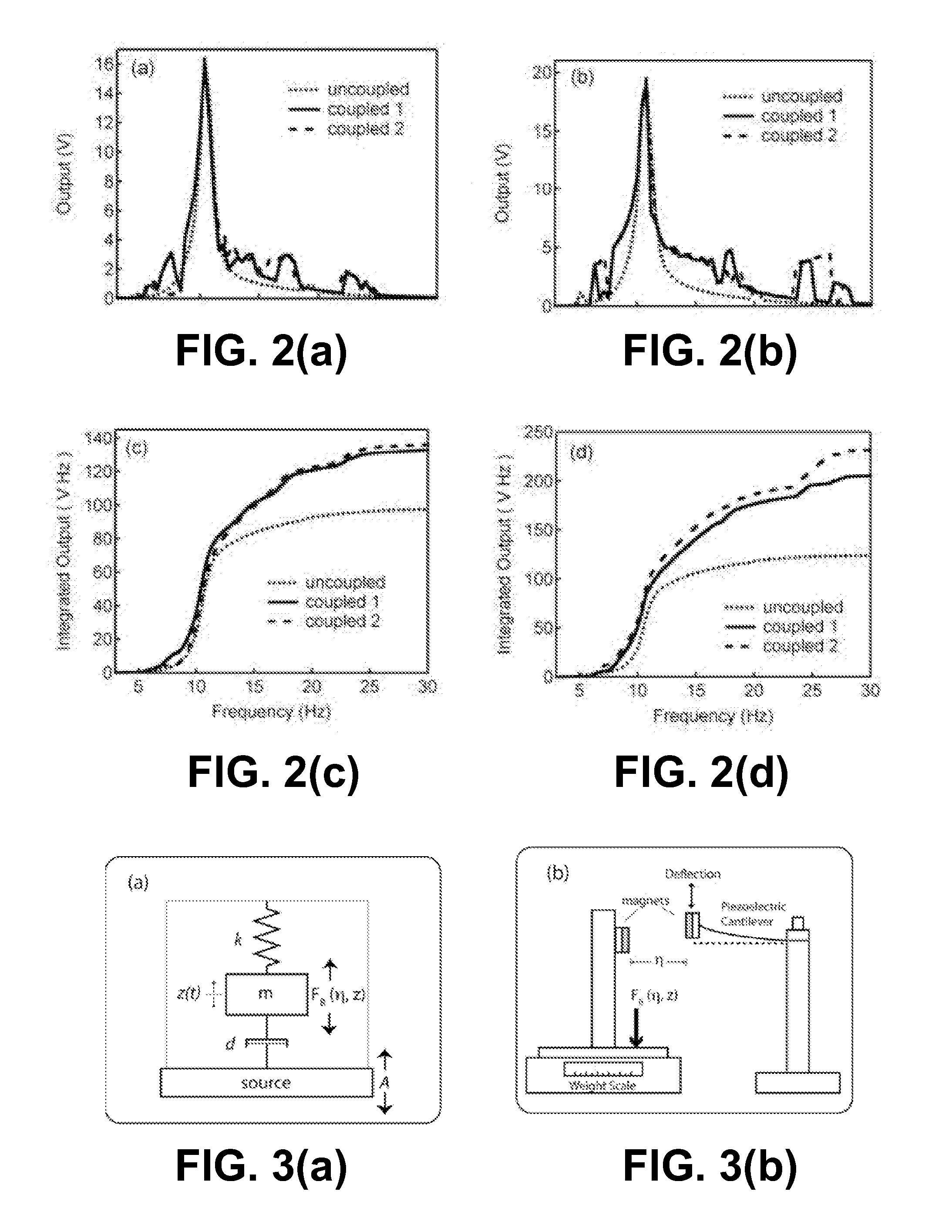
[0073]The set-up of FIG. 1(a) was again used, this time with vibration generated by shaker table 14 driven by an amplified pink noise source. The pink noise was generated numerically, with amplitude and crest factor set to about −4 dB and about 1.41, respectively. The average shaker table acceleration was about 7.5 m / s2, independent of the magnetic coupling. A custom Labview data acquisition program measured output voltage from the cantilever beam and the acceleration from the shaker table, once every second. The voltage peak to peak (Vpp) was measured by an oscilloscope (Agilent 54624A), and the dc voltage was detected with a digital multi-meter (YOGOGAWA 7561). An about 4.8 mm diameter round rare earth magnet 18 (Radio Shack model 64-1895) was attached to the vibrating tip of the cantilever beam 12, while a similar opposing magnet 20 was attached directly to the shaker table frame, with repulsive force. The distance between the magnets 11 was adjusted to about ...


PUM


Abstract

Embodiments of the invention couple a non-linear force to a vibration element such as a piezoelectric cantilever to introduce chaotic, i.e., non-resonant vibration in the vibration element and thereby improve the non-resonant response of the vibration element. By doing so, the vibration element is responsive to a wider frequency range of vibrations and thus may be more efficient in scavenging energy in environments where the vibration frequency is not constant, e.g., in environment subject to multi-mode or random vibration sources.

Description

CROSS-REFERENCE TO RELATED APPLICATIONS[0001]This application claims priority to U.S. Patent Provisional Application Ser. No. 61 / 238,422 to Ji-Tzuoh Lin et al. entitled “LINEAR VIBRATION ELEMENT COUPLED WITH NON-LINEAR FORCE TO IMPROVE NON-RESONANT FREQUENCY RESPONSE” and filed on Aug. 31, 2009, which application is incorporated by reference herein.GOVERNMENT RIGHTS[0002]The invention was supported in whole or in part by Contract / Grant No. DE-FC26-06NT42795 from the Department of Energy and Contract / Grant No. DAAB07-03-D-B010 / TO-0198 from the United States Navy. The Government has certain rights in the invention.FIELD OF THE INVENTION[0003]The present invention relates to energy harvesting and vibration sensing, and in particular, to harvesting energy or otherwise generating an electrical signal responsive to a source of vibration.BACKGROUND OF THE INVENTION[0004]Scavenging energy from background mechanical vibrations in the environment has been proposed as a possible method to prov...

Claims


Application Information

Patent Timeline
IPC IPC(8): G01P15/09
CPCG01P15/09H01L41/1136H02N2/188H02K35/00H02K33/00H10N30/306
Inventor LIN, JI-TZUOHALPHENAAR, BRUCE
Owner UNIV OF LOUISVILLE RES FOUND INC
Why Eureka
Try Eureka