Pressure sensor

a sensor and pressure sensor technology, applied in the field of pressure sensors, can solve the problems of complex electrical connection between the sensor element and the evaluation electronics, and achieve the effect of simple conta

Active Publication Date: 2011-03-03
ROBERT BOSCH GMBH
View PDF6 Cites 9 Cited by
  • Summary
  • Abstract
  • Description
  • Claims
  • Application Information

AI Technical Summary

Benefits of technology

[0006]The present invention provides a simple to implement contacting variant which may be used to produce a reliable electrical connection between the sensor element and the evaluation electronics of a pressure sensor of the type under discussion here.
[0008]Accordingly, the contacting between the sensor element and evaluation electronics is made directly via media-resistant bonding wires without the interconnection of printed conductors on an additional carrier. This eliminates the processing and assembly of a corresponding carrier in the sensor housing, which significantly simplifies the manufacture of the pressure sensor of the present invention. The adjusting complexity caused by the interconnection of a carrier with printed conductors is also eliminated. Accordingly, the probability of adjusting errors in the manufacture of the pressure sensor of the present invention is reduced. The adjustment and assembly of the separating wall between the sensor element and the evaluation electronics are relatively non-critical due to the flexibility and ductility of the bonding wires.
[0010]In a particularly advantageous variant, receptacles, designed for example as indentations, are provided in the housing floor for the sensor element and the components of the evaluation electronics. This simplifies their positioning and assembly, and the housing floor thus also provides additional stability and protection for the sensor element and the components of the evaluation electronics. In the case of the sensor element, this protection may also be supplemented by a media-resistant protective sheath covering the sensor element.
[0011]Furthermore, it proves to be advantageous if a mounting surface is provided in the housing floor for the separating wall which is elevated compared to the mounting surfaces for the sensor element and for the components of the evaluation electronics. This elevation is advantageously dimensioned in such a way that the bonding wires are only very slightly bent or kinked—if at all—when the separating wall is assembled. If the bonding wires are designed in such a way that they are already placed on the elevation before the assembly of the separating wall, it proves to be advantageous to design the elevation or the mounting surface for the separating wall to be narrower than the separating wall to minimize the tensions of the bonding wires and prevent the bonding wires from being kinked. In the event that the bonding wires have not yet been placed on the mounting surface for the separating wall after the bonding process, the separating wall is advantageously made wider than the mounting surface to make tension-free guidance of the bonding wires possible.

Problems solved by technology

In actual practice, this type of electrical connection between the sensor element and evaluation electronics has proven to be very complex and subject to error, as it requires a ceramic carrier provided separately with media-resistant printed conductors and bonding wire connections, on the one hand between the sensor element and the printed conductors and on the other hand between the evaluation electronics and the printed conductors.

Method used


Image

  • Pressure sensor
  • Pressure sensor
  • Pressure sensor

Examples


Embodiment Construction

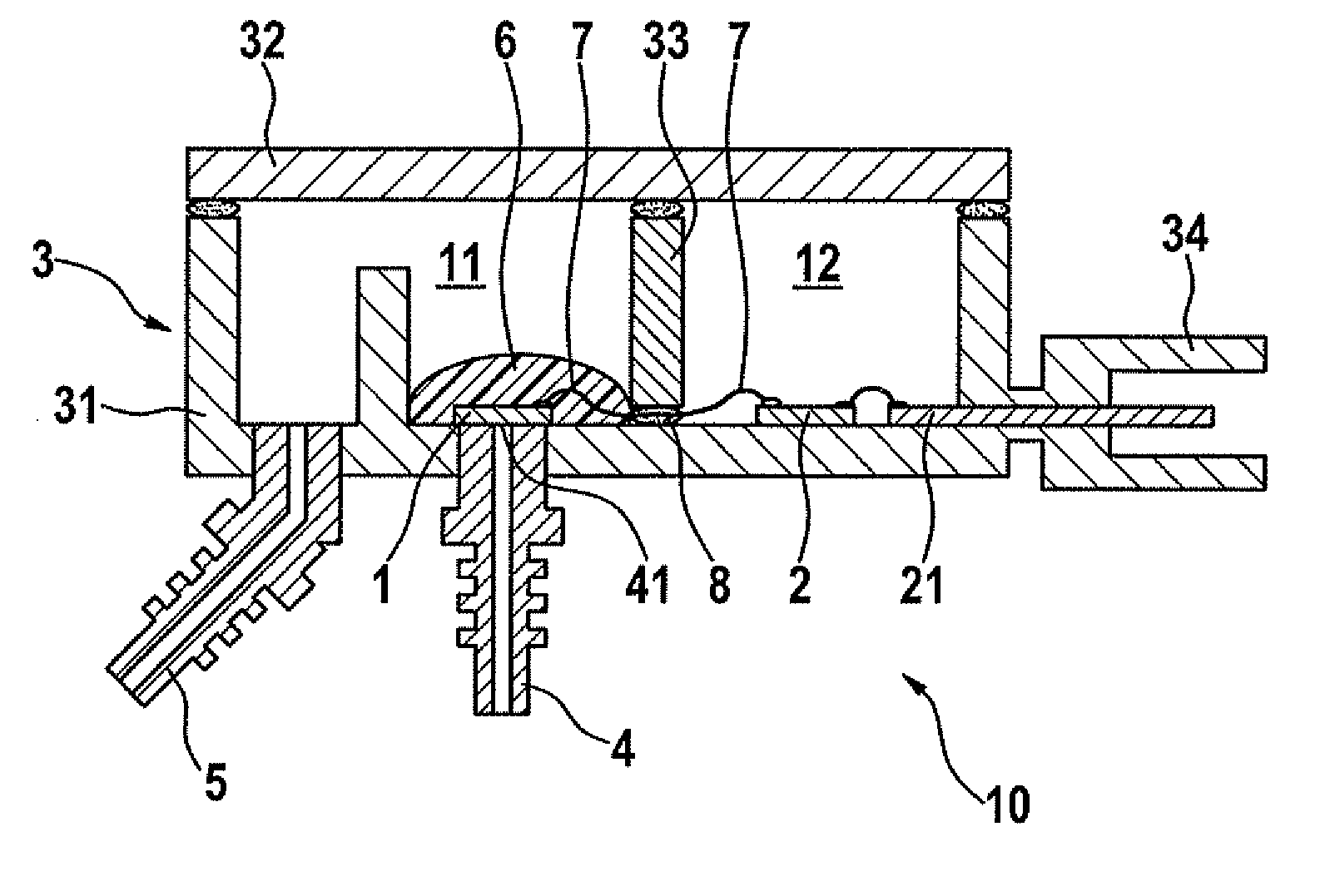
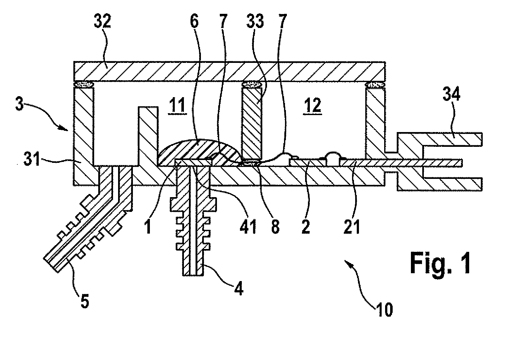
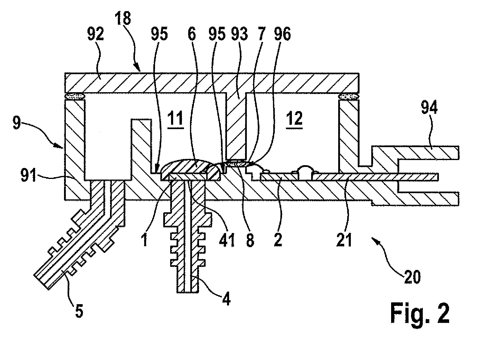
[0015]Pressure sensor 10 shown in FIG. 1 is used for detecting differential pressure in a corrosive measuring environment. It includes a media-resistant sensor element 1 and evaluation electronics which may include a plurality of components and are shown here as an additional component 2. Sensor element 1 is connected electrically to evaluation electronics 2 and is situated within housing 3. Sensor element 1 is located in a first housing area 11 having pressure connections 4 and 5, which is separated by a separating wall 33 from a second housing area 12 where evaluation electronics 2 and a plug connector part 21 are located for external contacting. Via pressure connection opening 41 of pressure connection 4, sensor element 1 is situated in such a way that a first measuring pressure is applied to the bottom of sensor element 1, while a second measuring pressure is present on the top of sensor element 1, the second measuring pressure being present within first housing area 11 due to p...


PUM

PropertyMeasurementUnit
pressureaaaaaaaaaa
areaaaaaaaaaaa
differential pressureaaaaaaaaaa

Abstract

A simple to implement contacting variant makes it possible to create a reliable electrical connection between the sensor element and the evaluation electronics of a pressure sensor, including at least one media-resistant sensor element, evaluation electronics in the form of at least one additional component connected electrically to the sensor element, and a multipart housing, the sensor element being situated in a first housing area having at least one pressure connection, and the evaluation electronics being situated in a second sealed housing area which is separated from the first housing area by a separating wall. The electrical connection between the sensor element and the evaluation electronics is implemented in the form of media-resistant bonding wires which are guided from the first into the second housing area through the bonded joint area between the separating wall and an additional housing part.

Description

FIELD OF THE INVENTION[0001]The present invention relates to a pressure sensor having at least one media-resistant sensor element, evaluation electronics in the form of at least one additional component electrically connected to the sensor element, and a multipart housing. The sensor element is situated in a first housing area having at least one pressure feed and the evaluation electronics are situated in a second sealed housing area which is separated from the first housing area by a separating wall.BACKGROUND INFORMATION[0002]Pressure sensors are used to detect the pressure or even the differential pressure in corrosive measuring environments. For example, the pressure determination upstream and downstream from a soot particle filter may be cited as a typical application from the automotive sector. The differential pressure may be used to determine the load of the soot particle filter and regulate the filter burn-off.[0003]In corrosive measuring environments, it is preferred to u...

Claims


Application Information

Patent Timeline
Patent Type & Authority Applications(United States)
IPC IPC(8): G01L7/00
CPCG01L19/0061G01L19/147G01L19/148H01L2224/48091H01L2224/8592H01L2224/48137H01L2924/00014
Inventor REINMUTH, JOCHENSCHMOLLNGRUBER, PETERARTMANN, HANS
Owner ROBERT BOSCH GMBH
Why Eureka
Try Eureka