
High reflectivity mirrors and method for making same

a high reflectivity, mirror technology, applied in the direction of instruments, optical elements, coatings, etc., can solve the problems of 5% or more of light being lost (i.e., absorbed) on each reflection, and the quantum efficiency of external reflection can be limited,

Active Publication Date: 2011-03-03
CREELED INC
View PDF75 Cites 43 Cited by
  • Summary
  • Abstract
  • Description
  • Claims
  • Application Information

AI Technical Summary

Benefits of technology

A method for fabricating a highly reflective element according an embodiment of the present invention comprises the following steps (in no particular order). A base element is provided. At least one transparent dielectric layer is deposited on the base element, the at least one diele

Problems solved by technology

For conventional LEDs with a single out-coupling surface, the external quantum efficiency can be limited by total internal reflection (TIR) of light from the LED emission region.
Some light may be absorbed by the reflector cup due to the less than 100% reflectivity of practical reflector surfaces.
The reflectivity at 0 degrees is lower than the reflectivity at 90 degrees, and this difference can result in 5% or more of the light being lost (i.e., absorbed) on each reflection.
In an LED chip, TIR light can reflect off the mirror several times before it escapes, and, as a result, small changes in the mirror reflectivity can lead to significant changes in the brightness of the LED.

Method used


Image

  • High reflectivity mirrors and method for making same
  • High reflectivity mirrors and method for making same
  • High reflectivity mirrors and method for making same

Examples


Embodiment Construction

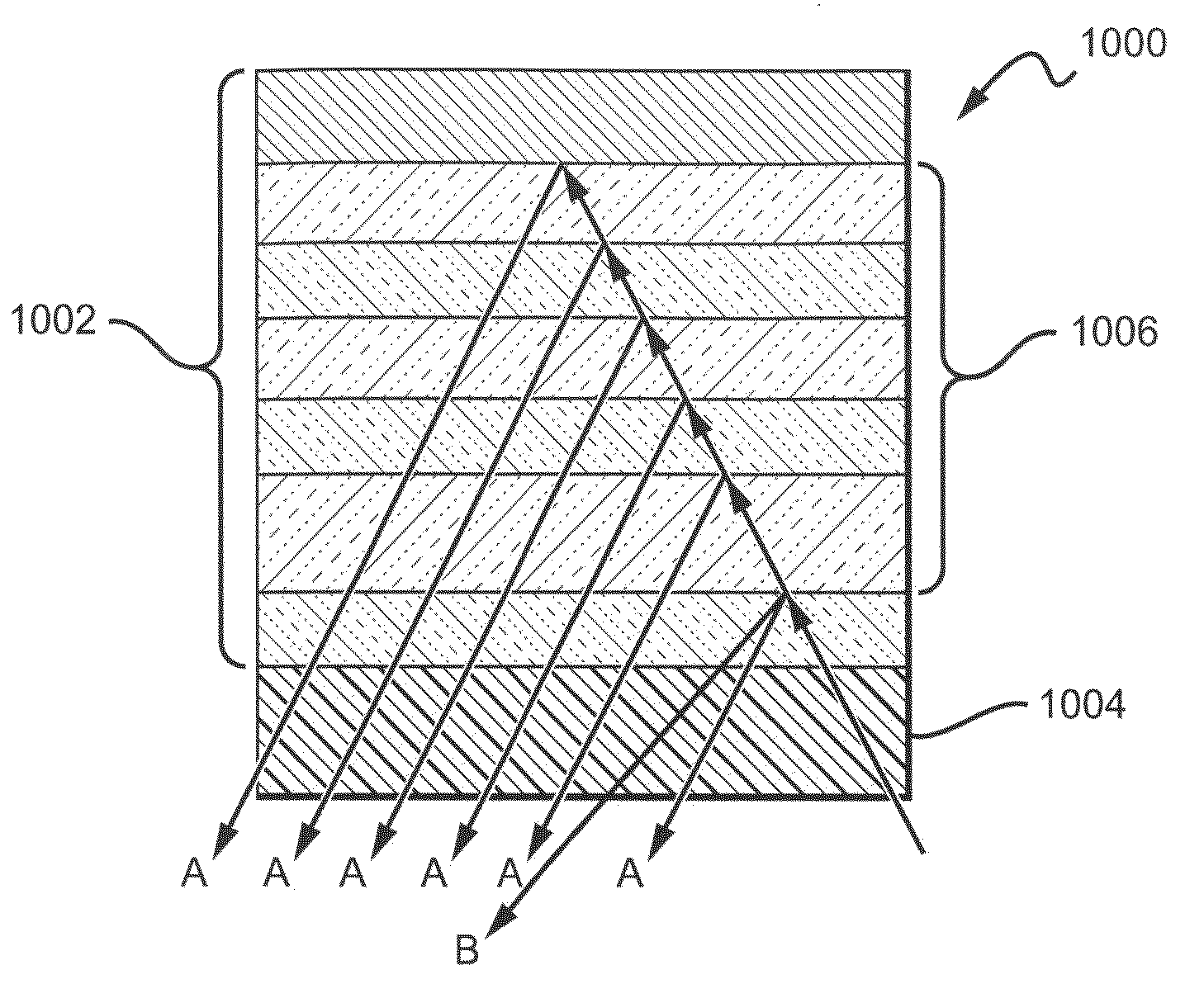
The present invention as embodied in the claims is directed to composite high reflectivity mirrors (CHRMs) with at least one relatively smooth interior surface interface. CHRMs are particularly well-suited for use in solid state light emitting devices such as LEDs or laser diodes. CHRM devices are discussed in detail in U.S. patent application Ser. No. 12 / 316,097 by Ibbetson, et al. which is commonly assigned with the present application to Cree, Inc., and which is incorporated by reference as if fully set forth herein. The CHRM materials may be used as contacts or layers arranged within the emitter devices to increase emission efficiency. Embodiments of the present invention are described herein with reference to LEDs, but it is understood that the concepts are equally applicable to other types of emitters. Embodiments of the present invention can be used as reflectors in conjunction with one or more contacts or can be used as a reflector separate from the contacts.

The improved ref...


PUM


Abstract

A composite high reflectivity mirror (CHRM) with at least one relatively smooth interior surface interface. The CHRM includes a composite portion, for example dielectric and metal layers, on a base element. At least one of the internal surfaces is polished to achieve a smooth interface. The polish can be performed on the surface of the base element, on various layers of the composite portion, or both. The resulting smooth interface(s) reflect more of the incident light in an intended direction. The CHRMs may be integrated into light emitting diode (LED) devices to increase optical output efficiency.

Description

BACKGROUND OF THE INVENTION1. Field of the InventionThis invention relates to composite high reflectivity mirrors and, more particularly, to such mirrors with one or more polished interior surfaces and methods for making the same.2. Description of the Related ArtLight emitting diodes (LED or LEDs) are solid state devices that convert electric energy to light, and generally comprise one or more active layers of semiconductor material sandwiched between oppositely doped n-type and p-type layers. When a bias is applied across the doped layers, holes and electrons are injected into the active layer where they recombine to generate light. Light is emitted from the active layer and from all surfaces of the LED.For typical LEDs it is desirable to operate at the highest light emission efficiency. One way that emission efficiency can be measured is by the emission intensity in relation to the input power in units of lumens per watt. One way to maximize emission efficiency is by increasing ex...

Claims


Application Information

Patent Timeline
IPC IPC(8): H01L33/00G02B5/08B05D5/06
CPCH01L33/387H01L33/46H01L33/405H01L2924/181H01L2224/48091H01L2224/48247H01L2224/73265H01L2924/00012H01L2924/00014H01L33/00H01L33/60H01L33/0062
Inventor HEIKMAN, STENJACOB-MITOS, MATTHEWLI, TINGIBBETSON, JAMES
Owner CREELED INC
Features
  • Generate Ideas
  • Intellectual Property
  • Life Sciences
  • Materials
  • Tech Scout
  • Unparalleled Data Quality
  • Higher Quality Content
  • 60% Fewer Hallucinations
Learn More