Fiber lasers

a fiber laser and fiber technology, applied in the field of fiber laser devices, systems and methods, can solve the problems of high thermal effects, inability to lase at the required wavelength, inability to achieve high power (kw cw) and moderate pulse energy (mj) pulse energy at band iv wavelengths, etc., to increase the overall conversion efficiency and increase the ability to wavelength selection

Active Publication Date: 2010-08-17
ELBIT SYST ELECTRO OPTICS ELOP
View PDF6 Cites 68 Cited by
  • Summary
  • Abstract
  • Description
  • Claims
  • Application Information

AI Technical Summary

Benefits of technology

[0006]According to one aspect of the, invention, there is provided a fiber laser for producing Band I wavelengths, including a laser cavity having an optical fiber with an inner clad, an outer clad surrounding the inner clad, and a core surrounded by the inner clad, the inner clad having at least pump power entry point, and the core having a lasing input / output end and a reflecting end, a first reflector positioned at the input / output end, and a second reflector positioned at the reflecting end, the first reflector having 90-100% reflectivity and the second reflector having more than 5% reflectivity in Band I, an energy source (also known as a pump source) for pumping power into the laser cavity via the pump power entry point, and a coupling mechanism for delivering the pump power from the energy source to the laser cavity. More specifically, this invention describes an efficient fiber laser to produce wavelengths longer than 2075 nm. An additional embodiment of this invention includes a mirror for the pump light to cause a second pass of pump light through the active fiber, thereby increasing the overall conversion efficiency and increasing the ability of wavelength selection.

Problems solved by technology

However, such fiber lasers have been thought to be highly inefficient or impossible to lase at the required wavelengths due to low gain, reabsorption by the active ion, or absorption of the host material.
However, fiber lasers with high powers (kW CW) and moderate (mJ) pulse energies (such as, for example, double clad fiber lasers) at Band IV wavelengths do not exist or are not practical for engineering.
However, the characteristics of the fiber (such as a 20 / 400 Yb fiber) dictate a fiber length of approximately 8 m, which can result in nonlinear effects such as stimulated Brillouin scattering (SBS), stimulated Raman scattering (SRS), and self-phase modulation (SPM) if high energy (mJ level) pulses are generated.
Furthermore, the OPO will not be able to handle generation of 4 W at 4 μm, particularly since the PPLN absorbs this wavelength, resulting in high thermal effects and instability.
Additionally, frequency conversion generally requires polarized laser sources, which are difficult and costly to assemble using nonstandard polarization maintaining components.

Method used


Image

  • Fiber lasers
  • Fiber lasers
  • Fiber lasers

Examples


example 1

Experiment: Long Wavelength Output Using Tm:Silica Fiber laser

[0076]In the following examples, a 20 / 200 Tm doped double clad silica fiber with the specifications listed in Table 2 was used.

[0077]

TABLE 2fibervalueCore size (μm)20Core NA0.11Clad size (μm)200Clad NA0.46Dopant conc.0.51026 atoms / m3Fiber length5Clad shapeoctagon

[0078]The laser performances of a given cavity with specified surface reflections were simulated at specific signal and pump wavelengths. The simulation tool which was used has the ability to predict both laser wavelength and efficiency curve, for both spectrally flat mirrors and for bulk grating (BG) mirrors.

[0079]Setup I.

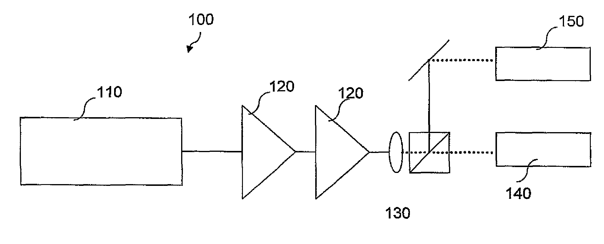
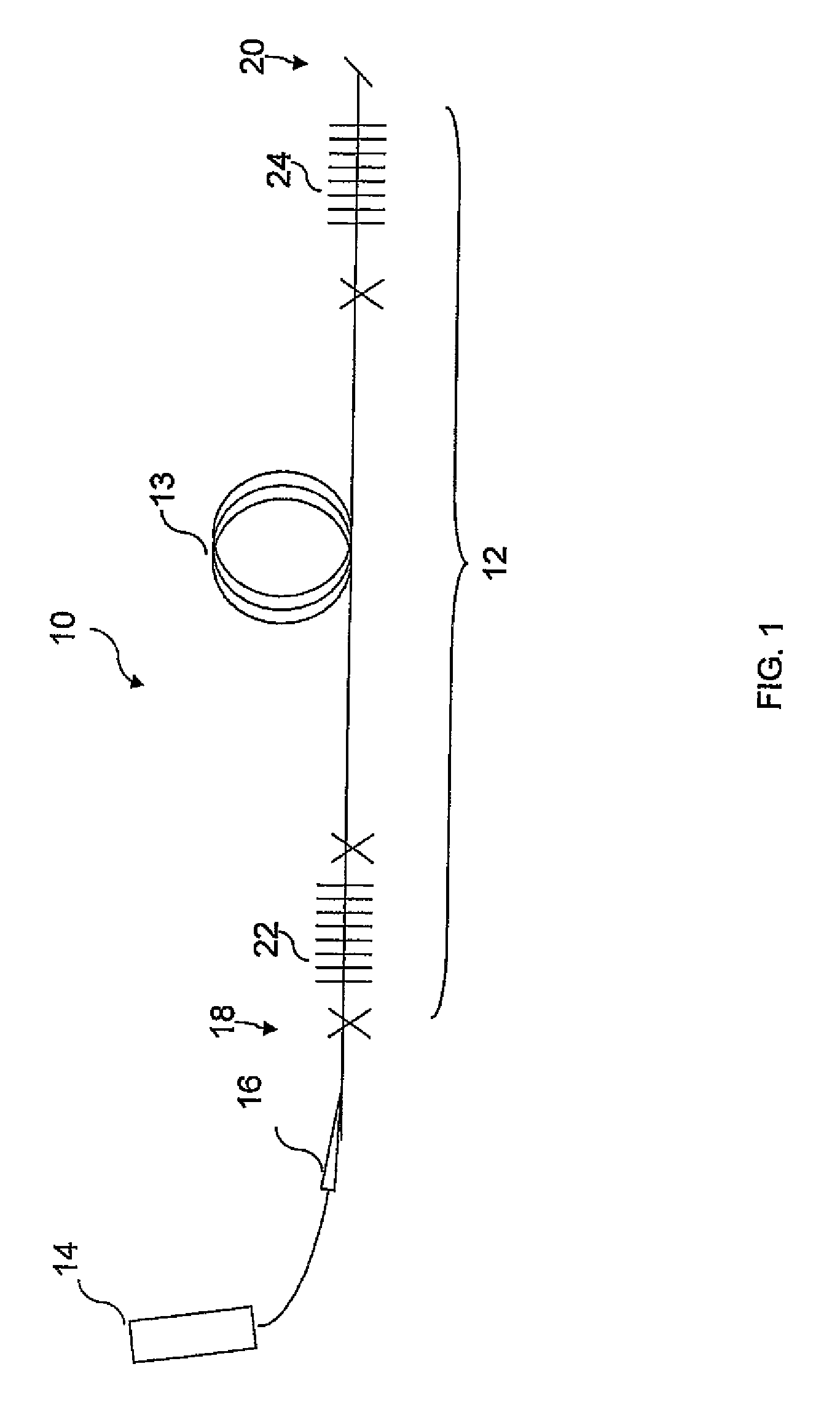
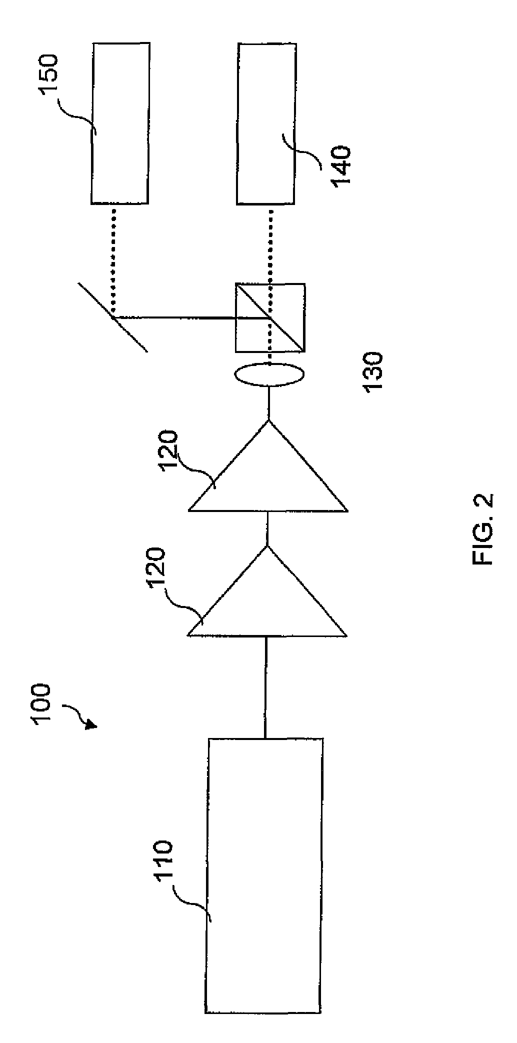
[0080]Reference is now made to FIG. 5, which is an illustration of a first setup of a fiber laser which was tested. Energy source 14 was a diode pump working at wavelength of approximately 790 nm. Coupling mechanism 16 was a free space beam combiner. First and second reflectors 22 and 24 were butted to flat dichroic mirrors, having characteristi...

example 2

Design Example: Influence of Parameters on Lasing Wavelength and Efficiency

[0104]As an example of selecting parameters, a 10 / 125 Tm fiber was selected. The lasing wavelength was fixed at 2095 nm, which is similar to Ho:YAG. Several different doping concentrations were tested. For each doping concentration, the fiber length and the reflectivity of the output coupler was varied. Parameters and values are listed in Table 7 below.

[0105]

TABLE 7ParameterUnitValueN (TmAtoms / m3variableconcentration)Core diameterμm10Clad diameterμm125Pump claddB / mvariableabsorptionSignal core lossdB / m0.22L (fiber length)mvariableR1 (reflectivity)%variableR2 (reflectivity)%80Pump powerW32Pump sideR1

The constraints are as follows:[0106]1) The maximum fiber length is 80-90% pump absorption in order to completely invert the gain media to ensure true CW lasing.[0107]2) The reflectivity of the mirror and length can then be selected for efficient operation for a given dopant concentration.

[0108]Reference is now mad...

example 3

Depolarization of Laser Diode

[0115]An externally stabilized signal laser diode (Lumics LU1064M150-1001002, S / N 51440) was used. In order to obtain a narrow spectrum in pulsed operation, the FBG was moved from about 1.8 m from the diode to about 60 cm from the diode. In addition, a polarization controller was placed between the FBG and the diode to ensure that alignment of the feedback from the FBG was aligned to the polarization of the diode. All CW measurements were performed at 300 mA of pump current. All pulsed measurements were performed at 100 ns pulse, 100 kHz, and 1.2 A peak current (ILX LDP-3840).

[0116]The diode was evaluated in CW and pulsed operation, with and without the depolarizer. Temporal traces and spectra were recorded.

[0117]Depolarization was done using a depolarizer setup as described above with reference to FIG. 3. A polarization controller was used in the experiment. A polarization analyzer was used for measuring the polarization state purity. Reference is now m...


PUM


Abstract

Fiber lasers for producing Band I wavelengths include a laser cavity having an optical fiber with specific parameters in length and thickness and doping concentration, and having high reflectivities. Examples show the feasibility of producing such fiber lasers. Fiber lasers for producing Band IV wavelengths include a depolarized laser oscillator, at least one amplifier and a polarizer. Depolarized laser oscillator is an inherently depolarized CW laser, or a depolarized laser diode, which is depolarized by a depolarizer. Additional fiber lasers in accordance with embodiments of the present invention include a double clad active optical fiber having a pump power entry point for sending pump energy through the active optical fiber in a first direction, and a loop portion at a second end of the fiber for sending pump energy through the active optical fiber in a second direction which is opposite to the first direction. A system for coupling light into a fiber in accordance with embodiments of the present invention include a first fiber, a second double clad fiber, and a bulk optic component positioned between the first and second fibers. A mode stripper included within the second fiber allows for removal of high power light which is propagated through the outer clad rather than launched into the core of the second fiber.

Description

RELATED APPLICATION DATA[0001]This application is a Continuation-In-Part (CIP) application to co-pending patent application Ser. No. 12 / 088,987 filed on Apr. 2, 2008, which is the U.S. National Stage of PCT / IL2006 / 001090 filed on Aug. 18, 2006, which is based on and claims the benefit of Israeli Application No. 171251 filed on Oct. 2, 2005, the content of each of which is expressly incorporated herein in its entirety by reference hereto.FIELD OF THE INVENTION[0002]The present invention relates to fiber laser devices, systems and methods, more particularly, to fiber laser devices, systems and methods for producing Band I and Band IV wavelengths.BACKGROUND OF THE INVENTION[0003]Lasers for use in the Band I range of wavelengths are suitable for many applications such as remote sensing, laser radar, directed infrared countermeasures, and others. Typically, lasers which are capable of working in the Band I range are bulk lasers made from crystals. It would be advantageous to have Band I ...

Claims


Application Information

Patent Timeline
Patent Type & Authority Patents(United States)
IPC IPC(8): H01S3/10
CPCH01S3/06716H01S3/06729H01S3/1616H01S3/0677H01S3/094003H01S3/0675
Inventor SACKS, ZACHARYSCHIFFER, ZEEV
Owner ELBIT SYST ELECTRO OPTICS ELOP
Why Eureka
Try Eureka