Light recycling illumination systems utilizing light emiting diodes

a technology of light-emitting diodes and illumination systems, which is applied in the direction of discharge tubes luminescnet screens, lighting and heating apparatus, instruments, etc., can solve the problems of lowering the overall efficiency of illumination systems, unable to disclose illumination systems without light-emitting cavities or envelopes, and reducing the effective brightness of illumination systems. , to achieve the effect of increasing the effective brightness and the output efficiency of illumination systems

Inactive Publication Date: 2006-03-30
GOLDENEYE
View PDF15 Cites 66 Cited by
  • Summary
  • Abstract
  • Description
  • Claims
  • Application Information

AI Technical Summary

Benefits of technology

[0009] This invention is an illumination system that incorporates a light emitting diode and a partially reflecting optical element. The light emitting diode emits internally generated light and reflects incident light with high reflectivity. The partially reflecting optical element transmits a first portion of the internally generated light and reflects a second portio

Problems solved by technology

Any emitted light that does get back to the source is absorbed and lost, lowering the overall efficiency of the illumination system.
The three aforementioned applications di

Method used


Image

  • Light recycling illumination systems utilizing light emiting diodes
  • Light recycling illumination systems utilizing light emiting diodes
  • Light recycling illumination systems utilizing light emiting diodes

Examples


Embodiment Construction

[0017] The preferred embodiments of the present invention will be better understood by those skilled in the art by reference to the above figures. The preferred embodiments of this invention illustrated in the figures are not intended to be exhaustive or to limit the invention to the precise form disclosed. The figures are chosen to describe or to best explain the principles of the invention and its applicable and practical use to thereby enable others skilled in the art to best utilize the invention.

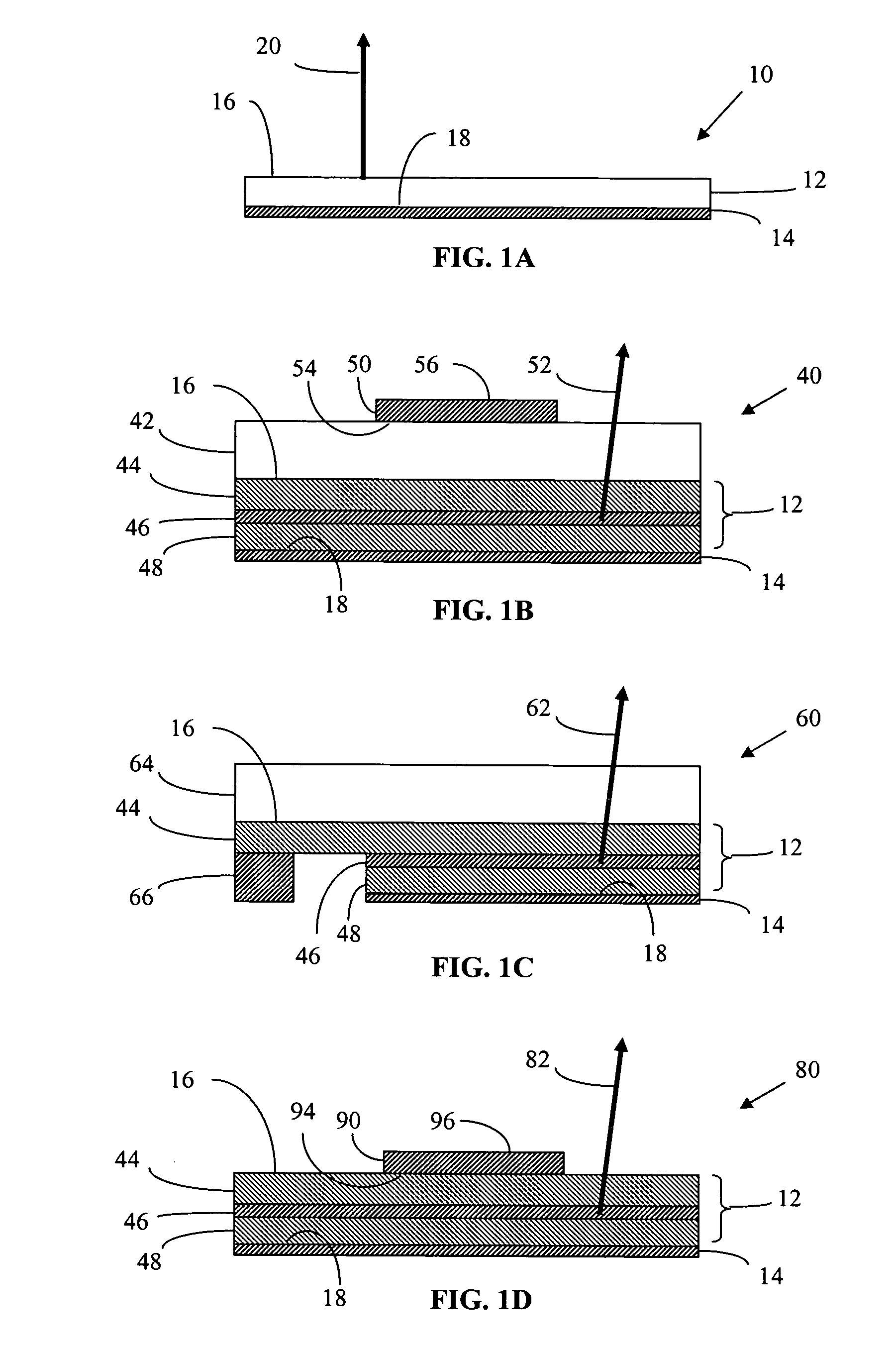
[0018] An LED of this invention incorporates a multi-layer semiconductor structure that emits light. Inorganic light-emitting diodes can be fabricated from materials containing gallium nitride (GaN), including the materials aluminum gallium nitride (AlGaN) and indium gallium nitride (InGaN). Other appropriate LED materials are aluminum nitride (AlN), aluminum indium gallium phosphide (AlInGaP), gallium arsenide (GaAs), indium gallium arsenide (InGaAs) or indium gallium arsenide phosphi...


PUM


Abstract

This invention is an illumination system that incorporates a light emitting diode and a partially reflecting optical element. The light emitting diode emits internally generated light and reflects incident light with high reflectivity. The partially reflecting optical element transmits a first portion of the internally generated light and reflects a second portion of the internally generated light back to the light emitting diode, where the second portion is reflected by the light emitting diode. The partially reflecting optical element can be a non-absorbing reflecting polarizer or a wavelength conversion layer. Utilizing a partially reflecting optical element and light recycling can increase the effective brightness and the output efficiency of the illumination system.

Description

CROSS REFERENCES TO RELATED APPLICATIONS [0001] This application is related to U.S. patent application Ser. No. 10 / 445,136 entitled “ILLUMINATION SYSTEMS UTILIZING HIGHLY REFLECTIVE LIGHT EMITTING DIODES AND LIGHT RECYCLING TO ENHANCE BRIGHTNESS,” to U.S. patent application Ser. No. 10 / 814,043 entitled “ILLUMINATION SYSTEMS UTILIZING LIGHT EMITTING DIODES AND LIGHT RECYCLING TO ENHANCE OUTPUT RADIANCE” and to U.S. patent application Ser. No. 10 / 814,044 entitled “ILLUMINATION SYSTEMS UTILIZING MULTIPLE WAVELENGTH LIGHT RECYCLING,” all of which are herein incorporated by reference. [0002] This application is also related to U.S. patent application Ser. No. ______ entitled 37 LIGHT EMITTING DIODES EXHIBITING BOTH HIGH REFLECTIVITY AND HIGH LIGHT EXTRACTION,” and U.S. patent application Ser. No. ______ entitled “LIGHT RECYCLING ILLUMINATION SYSTEMS HAVING RESTRICTED ANGULAR OUTPUT,” all of which are filed concurrently with this application and are herein incorporated by reference.TECHNI...

Claims


Application Information

Patent Timeline
IPC IPC(8): H01J5/16H01J61/40H01L33/44H01L33/60
CPCG02B27/28H01L33/60H01L33/44Y10S362/80
Inventor BEESON, KARL W.ZIMMERMAN, SCOTT M.
Owner GOLDENEYE
Why Eureka
Try Eureka