Capacitive sensor and actuator

a technology of capacitive sensors and actuators, applied in the direction of resistance/reactance/impedence, instruments, microstructural devices, etc., can solve the problems of additional electrodes and severely limited dynamic range, and achieve the effect of simple manner

Inactive Publication Date: 2011-03-03
ROBERT BOSCH GMBH
View PDF8 Cites 59 Cited by
  • Summary
  • Abstract
  • Description
  • Claims
  • Application Information

AI Technical Summary

Benefits of technology

[0016]In a further specific embodiment of the present invention, the geometry of the at least one comb electrode is optimized via a pre

Problems solved by technology

However, for plate capacitors of the related art the shape of the characteristic curve is strictly specified, so that the dynamic range is severely limited.
However, a disadvantage of such differential c

Method used


Image

  • Capacitive sensor and actuator
  • Capacitive sensor and actuator

Examples


Embodiment Construction

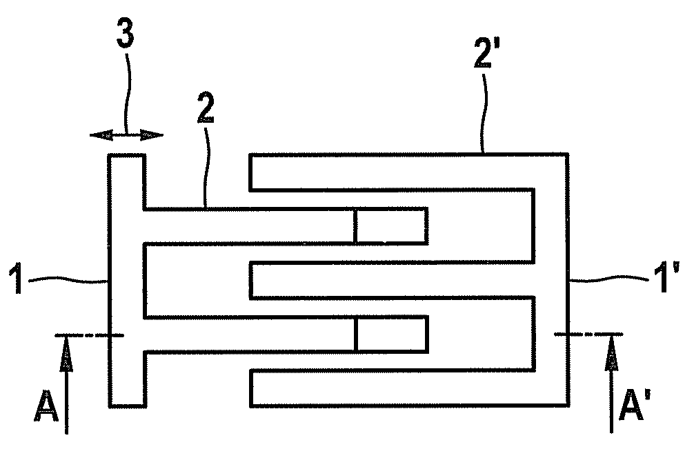
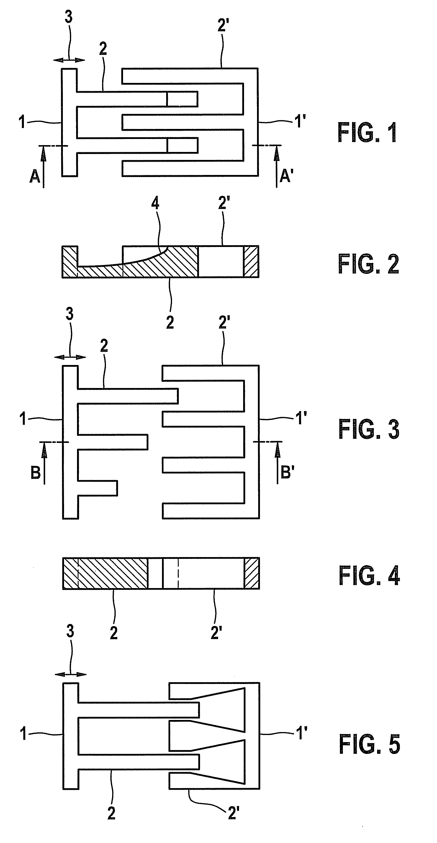
[0023]The capacitive sensor according to FIG. 1 includes a seismic mass (not illustrated) which is deflectably mounted on an immovable substrate, or possibly mounted on an additional movable mass. The deflectability of the seismic mass may be achieved, for example, by mounting the seismic mass on the substrate, using one spring or multiple springs having a defined stiffness. A first comb electrode 1 having multiple comb fingers 2 is also mounted on the seismic mass, and a second comb electrode 1′ having multiple comb fingers 2′ is mounted on the substrate or the additional movable mass. Comb fingers 2 and 2′ of comb electrodes 1 and 1′, respectively, are aligned in parallel, and interlock in a comb-like manner in such a way that in the neutral state they form an overlap area. Comb fingers 2 and 2′ thus form a capacitor, the overlap surface being the effective surface area for the capacitance of the capacitor.

[0024]Comb electrodes 1 and 1′ are also mounted on the seismic mass or the ...


PUM


Abstract

A capacitive sensor and a capacitive actuator having at least one seismic mass deflectably mounted on a substrate. A comb electrode having comb fingers is mounted on the seismic mass, and a comb electrode having comb fingers is mounted on the substrate in such a way that the comb fingers are situated parallel to a deflection direction of the seismic mass and interlock in a comb-like manner. The characteristic curve of the sensor or actuator is adjusted by optimizing the geometry of at least one comb electrode, in particular of at least one comb finger.

Description

FIELD OF THE INVENTION[0001]The present invention relates to a capacitive sensor and actuator having at least one seismic mass deflectably mounted on a substrate, a comb electrode having comb fingers being mounted on the seismic mass, and a comb electrode having comb fingers being mounted on the substrate, and the comb fingers being situated parallel to a direction of the deflection of the seismic mass and interlocking in a comb-like manner.BACKGROUND INFORMATION[0002]Sensors are known in many fields of technology. Micromechanical sensors are used, for example, in automotive, industrial, and medical technology, as well as in many areas of consumer electronics, in particular as acceleration, rotational speed, or pressure sensors. Capacitive sensors in particular are widely used.[0003]Capacitive sensors are based on a spring-mass system in which a seismic mass is deflected with respect to a substrate, against a predetermined restoring force, for example as the result of acceleration o...

Claims


Application Information

Patent Timeline
IPC IPC(8): G01R27/26
CPCB81B3/0094B81B2201/0221B81B2201/0235H02N1/008G01D5/2412G01P15/125B81B2201/033
Inventor FRANKE, AXELBUHMANN, ALEXANDERKECK, MARIAN
Owner ROBERT BOSCH GMBH
Why Eureka
Try Eureka