Traveling unit driving apparatus and image reading apparatus provided with the driving apparatus

Active Publication Date: 2011-03-03
NISCA KK
View PDF16 Cites 10 Cited by
  • Summary
  • Abstract
  • Description
  • Claims
  • Application Information

AI Technical Summary

Benefits of technology

[0019]The advantageous effects of the invention will be described. In the invention, the driving belt extended between a pair of pulleys is formed of the belt with ends and teeth, and it is thereby possible to mass-produce the belt as an open belt with the belt length provided irrespective of apparatus specifications of a used traveling unit. Therefore, it is not necessary to prepare manufacturing equipment such as a manufacturing die corresponding to apparatus specifications, the belt can be cut into the length corresponding to the apparatus specifications and used, and it is possible to remarkably reduce the manufacturing cost.
[0020]Further, the structure for fixing the belt with teeth to the traveling unit is the mechanism for adjusting the length with the belt tooth surface of the belt end portions engaged in protrusions provided in the first and second engagement portions, and locking the protrusions of the lock fixing member in the belt tooth surface with the end portions bent substantially in the orthogonal direction, the fixing operation is thereby ease, and concurrently therewith, skills are not required to adjust the belt length and adjust the tension.
[0021]P

Problems solved by technology

Then, in the case of the wire, it is known there are problems such as a kink and position displacement of the winding pulley, and in the case of the belt with teeth, it is known there is a problem in manufacturing accuracy of the belt.
However, in the case of the wire, when a position displacement arises in winding by a winding pulley, a winding amount changes and fluctuations in velocity occur in the traveling unit.
Concurrently therewith, a kink tends to occur in the wire in winding, and it is known there is a problem in durability.
Meanwhile, when the belt with teeth such as a timing belt is used, it is known there is a problem in dimension accuracy in manufacturing the belt.
Therefore, when the belt is coupled to the traveling unit simply by screw, through pin or the like, a coupling hole is broken (by the effect of the r

Method used


Image

  • Traveling unit driving apparatus and image reading apparatus provided with the driving apparatus
  • Traveling unit driving apparatus and image reading apparatus provided with the driving apparatus
  • Traveling unit driving apparatus and image reading apparatus provided with the driving apparatus

Examples


Embodiment Construction

Configuration of an Optical Carriage

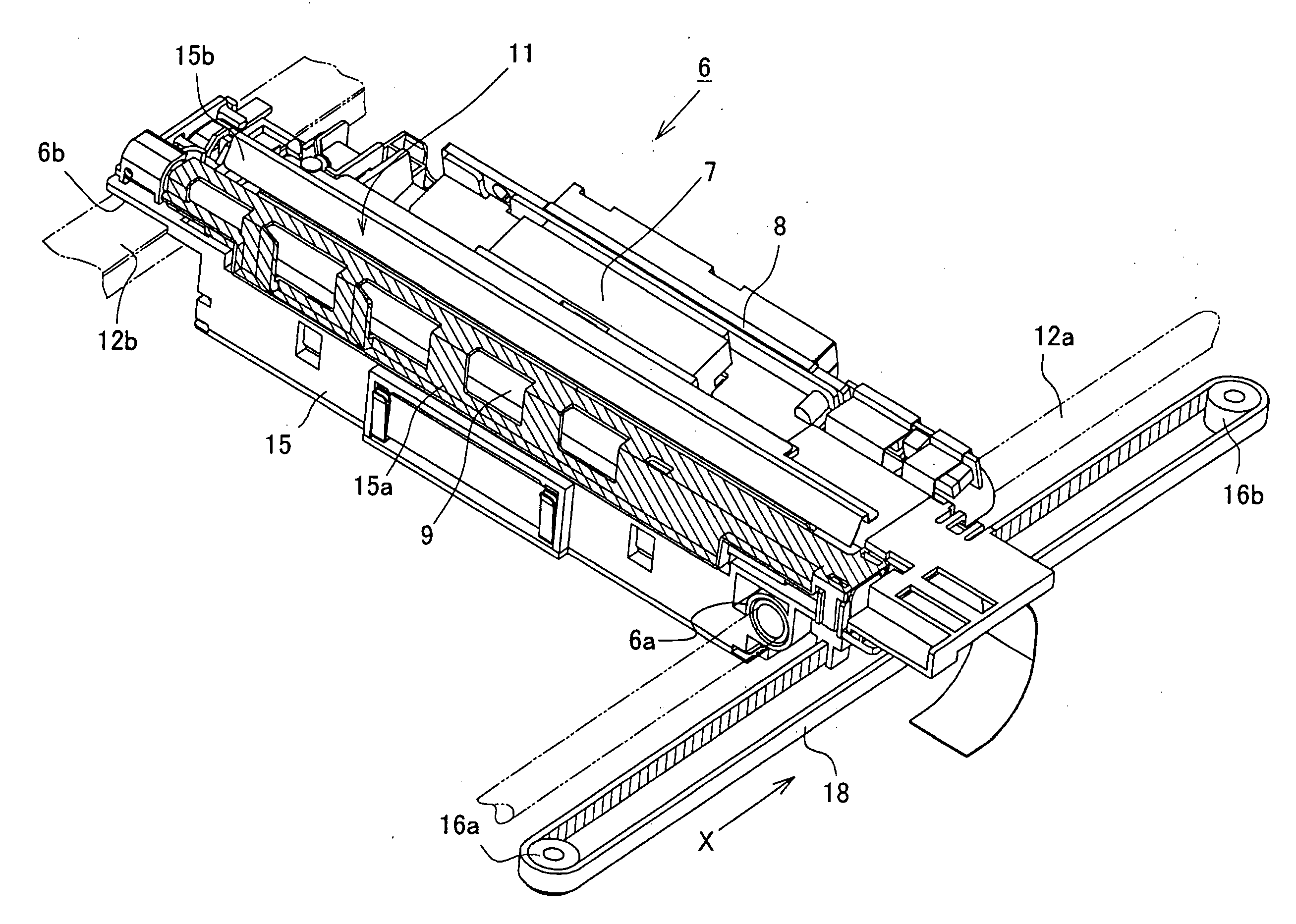
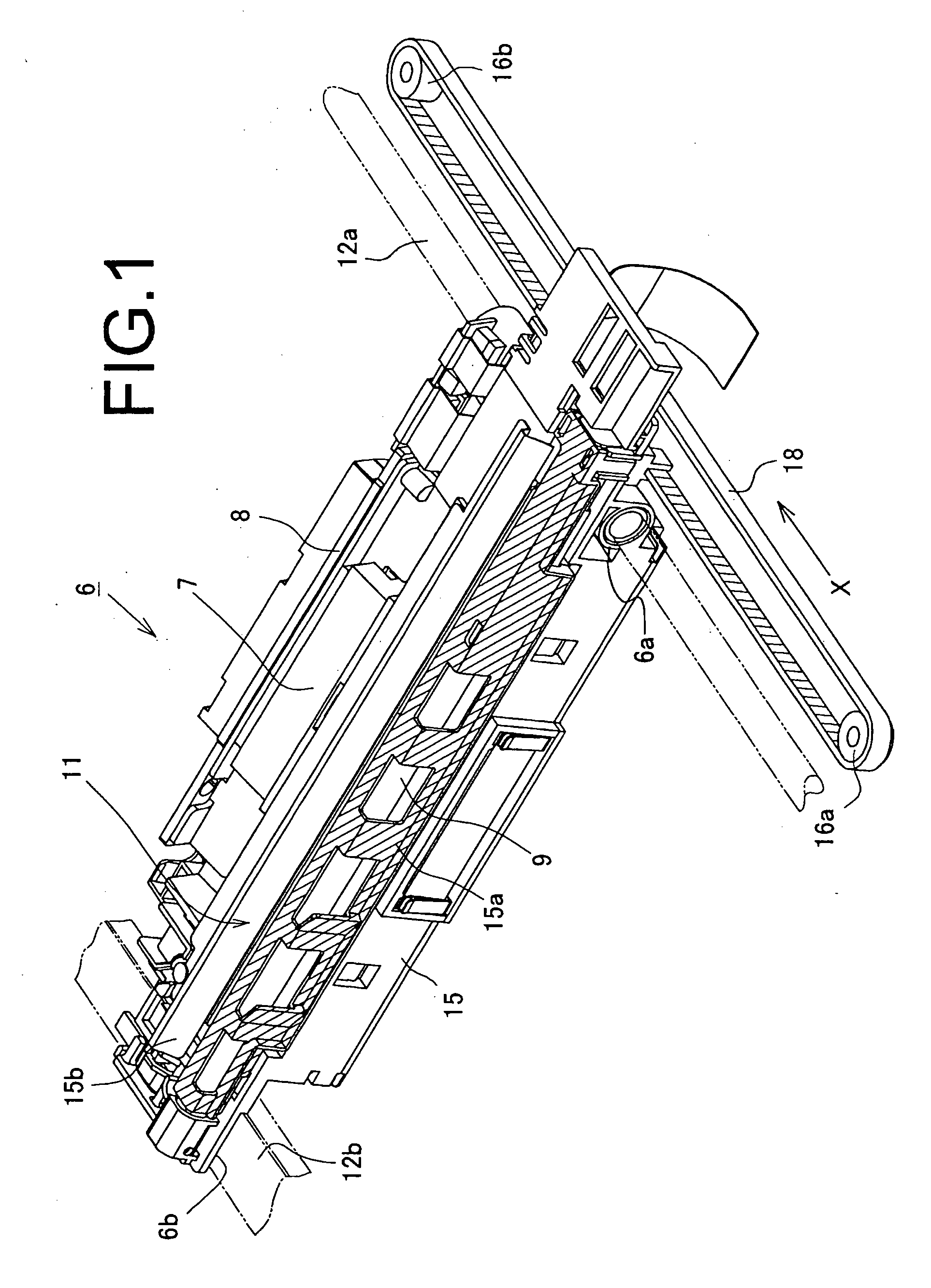
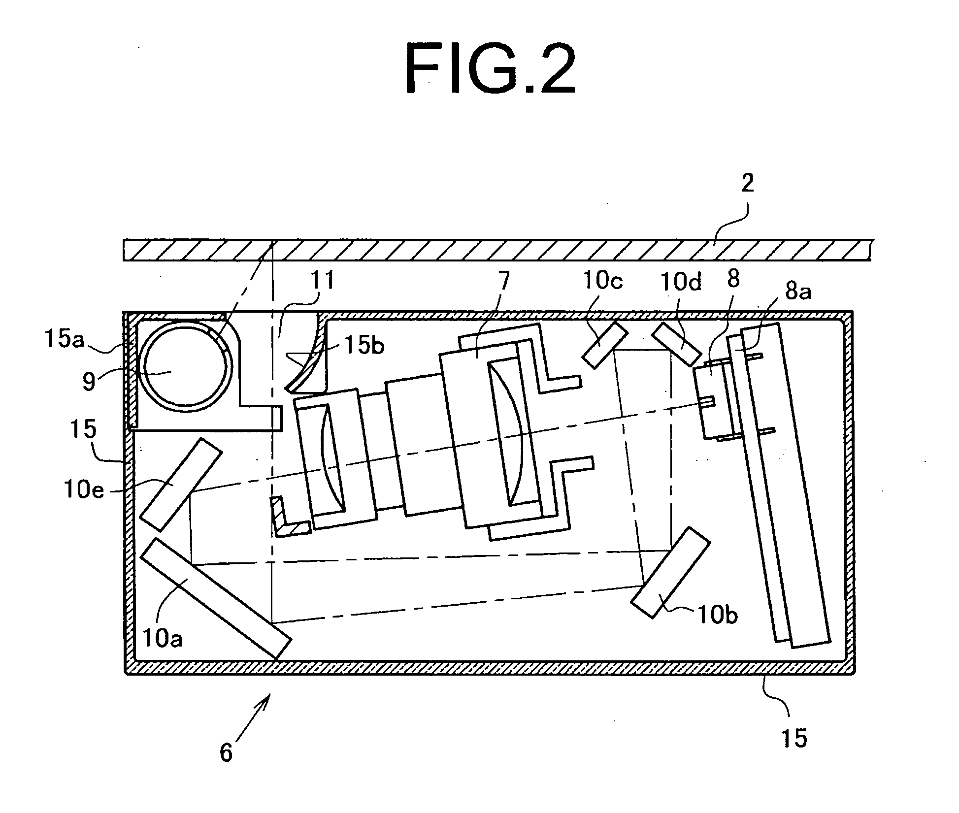
[0029]FIG. 1 is an explanatory view of the entire configuration of an image reading apparatus provided with a driving apparatus for a traveling unit such an optical carriage. FIG. 2 is a structure explanatory view of the inside of the optical carriage, and FIG. 3 is a perspective explanatory view showing the relationship between the platen and optical carriage. Described below are a traveling unit structure and driving belt structure in this order.

[Carriage (Traveling Unit) Structure]

[0030]Described first is a configuration of the traveling unit (hereinafter, referred to as an optical carriage) according to the invention. As shown in FIG. 1, an optical carriage 6 is comprised of a carriage frame 15, light source 19, reflecting mirrors 10, condenser lens 7, and image reading sensor 8. The carriage frame 15 is formed of, for example, a resin high in heat resistance, and mounted with the light source lamp 9, imaging devices (reflecting mirrors and co...


PUM


Abstract

Provided is a traveling unit driving apparatus where a driving belt of the traveling unit is manufactured with ease, and concurrently therewith, can be coupled reliably to the unit in a state with high durability.
A driving belt extended between a pair of pulleys is formed using a belt with ends and teeth, and a belt fixing means is comprised of a first and second engagement portions provided in the traveling unit, a concave recess portion disposed between the portions, and a lock fixing member that is fitted into the concave recess portion. Then, the first and second engagement portions and the concave recess portion are provided with a first and second mount surfaces for bending and supporting the belt opposite end portions, the lock fixing member is fitted into the concave recess portion, and the belt opposite end portions are thereby sandwiched and held in a bent state. Concurrently therewith, the first and second engagement portions and the lock fixing member are respectively provided with protrusions for engaging in the belt tooth surface.

Description

BACKGROUND OF THE INVENTION[0001]1. Technical Field[0002]The present invention relates to improvements in a driving mechanism for causing a traveling unit to reciprocate in an apparatus provided with the traveling unit such as an image reading carriage that reciprocates with a predetermined stroke.[0003]2. Description of the Related Art[0004]Generally, in this type of image reading apparatus i.e. image reading apparatus such as a copier and scanner apparatus, in reading an original document image set on a platen, an optical carriage is mounted with a light source for emitting reading light, and an image reading sensor performs photoelectric conversion on the reflected light from the original document. Therefore, the optical carriage mounted with the light source and reflecting mirrors reciprocates along an image reading area of the platen to scan the original document image.[0005]Therefore, the optical carriage has a frame inappropriate form mounted with a light source lamp and refl...

Claims


Application Information

Patent Timeline
IPC IPC(8): H04N1/04F16G11/00
CPCF16G3/06H04N1/103H04N1/1026H04N1/1017
Inventor HIROKAWA, HIROYUKIENOMOTO, SHINNOSUKEDOHI, MAMORU
Owner NISCA KK
Why Eureka
Try Eureka