
Structure For Optical Pickup Head

a pickup head and optical technology, applied in the direction of optical recording heads, instruments, data recording, etc., can solve the problem of laser diodes with strong noise problems, and achieve the effect of reducing or eliminating the noise problem of laser diodes

Inactive Publication Date: 2011-03-03
TOPRAY MEMS
View PDF7 Cites 1 Cited by
  • Summary
  • Abstract
  • Description
  • Claims
  • Application Information

AI Technical Summary

Benefits of technology

[0006]The primary object of the present invention is to reduce or eliminate the noise problem for the laser diode caused by the feedback light of the recording medium.
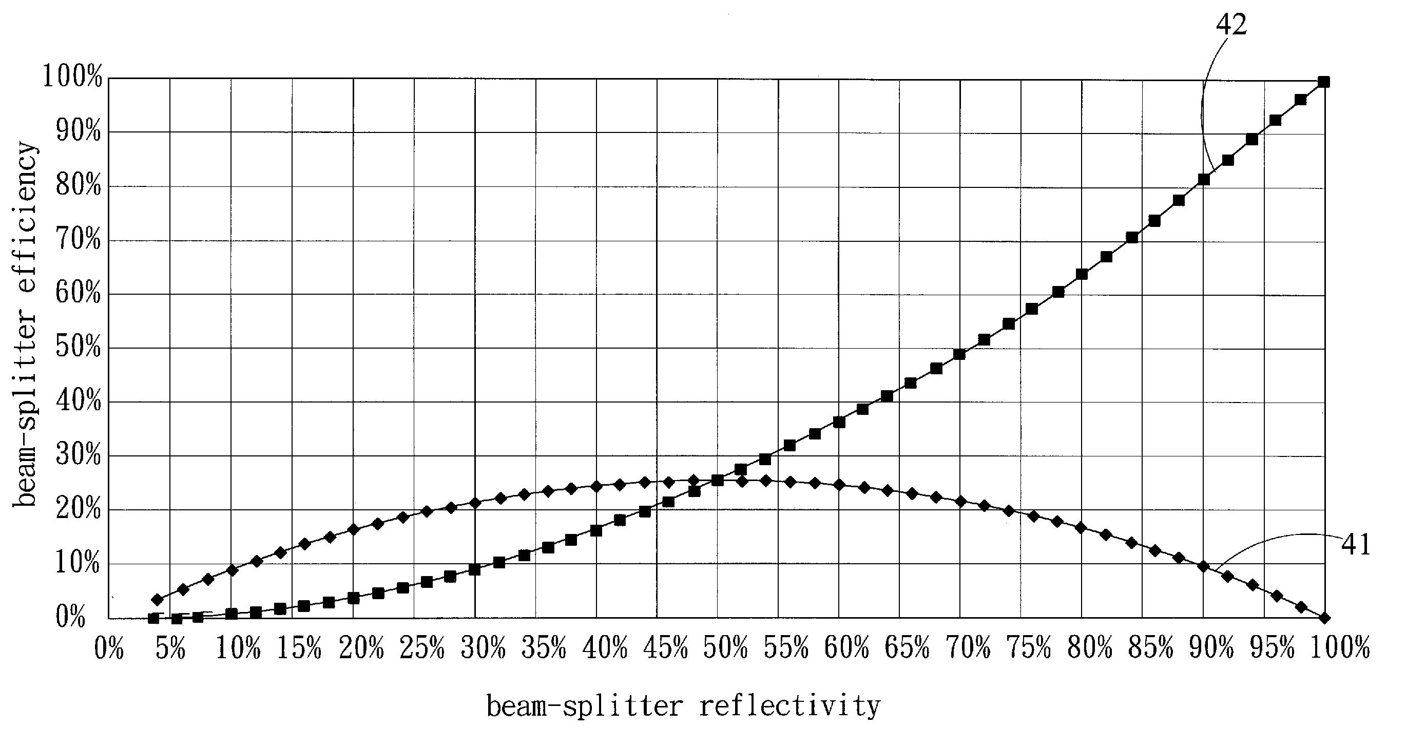
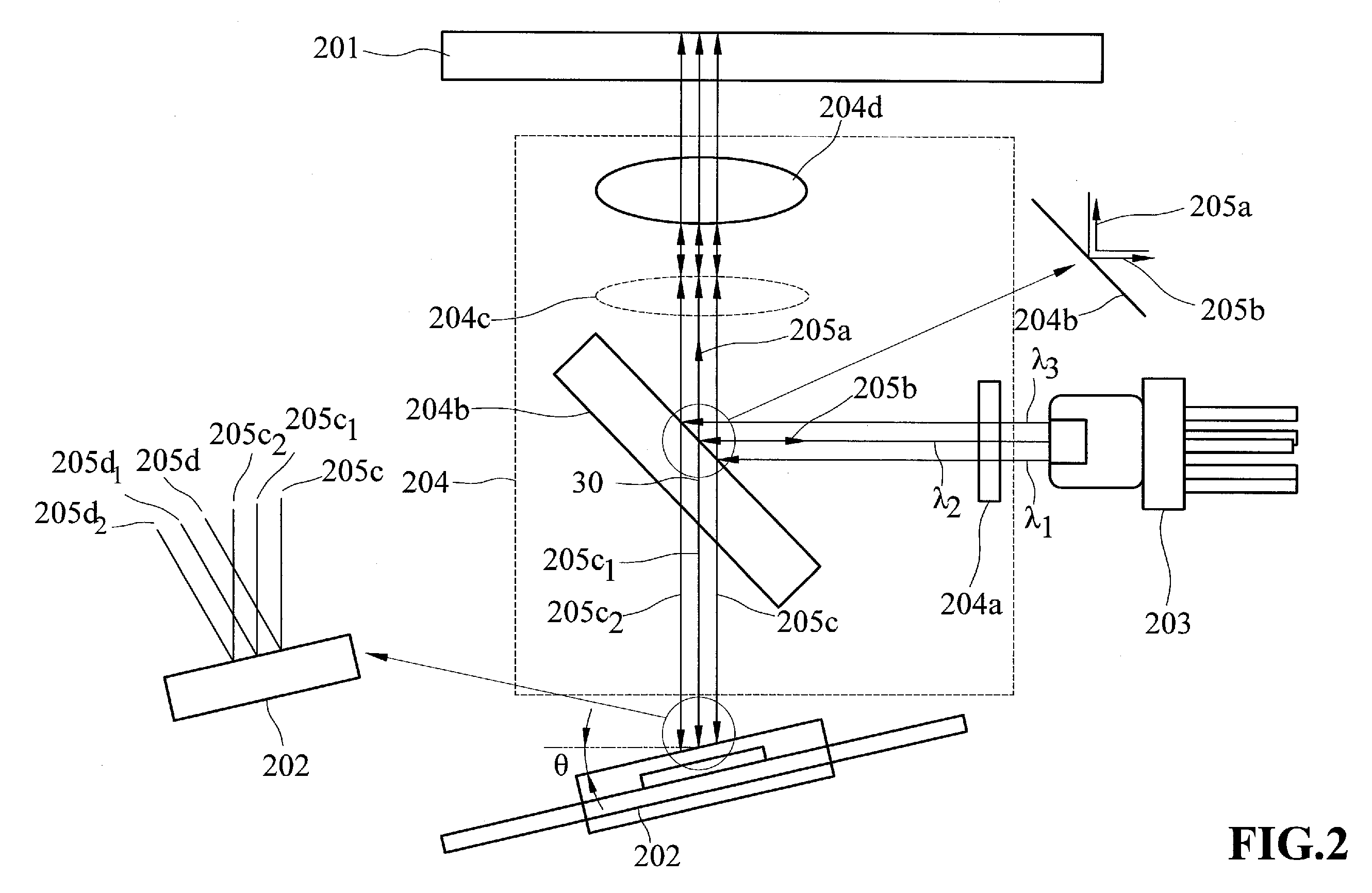
[0008]The optical element set includes a low reflectivity beam-splitter, and an objective lens. The low reflectivity beam-splitter has the capability of both reflecting and transmitting the laser light. The objective lens is for focusing the laser light on the recording medium. The optical element set further includes a grating to split a light beam into three light beams. The optical element set also further includes a coupling lens to adjust the collimation of the laser beam and improve the optical efficiency. The low reflectivity beam-splitter of the present invention has the average reflectivity ranging from 10% to 30%, and reflects the laser light twice to reduce the aforementioned noise source 1 for laser diode set 103. Moreover, with the optical signal detector having an 3° to 15° ranging θ tilt to the optical axis to reduce the aforementioned noise source 2 for the laser diode set, the optical pickup head of the present invention can achieve the object of reducing or eliminating the noise problem of the laser diode caused by the feedback light from the recording medium.
[0009]The low reflectivity beam-splitter of the present invention is cost effective, and the optical signal detector having an 3° to 15° ranging θ tilt to the optical axis shows technological improvement. With one or the combination of the two features, the present invention can effectively reduce or eliminate the feedback light and solve the existing noise problem for the laser diode.

Problems solved by technology

Therefore, the laser will have strong noise problem.

Method used


Image

  • Structure For Optical Pickup Head
  • Structure For Optical Pickup Head
  • Structure For Optical Pickup Head

Examples


Embodiment Construction

[0015]FIG. 2 shows a schematic view of an optical pickup head according to the present invention. As shown in FIG. 2, an optical pickup head includes a recording medium 201, an optical signal detector 202, a laser diode set 203, and an optical element set 204. Laser diode set 203 is a laser light source with single, two or three different wavelengths. Optical element set 204 includes a low reflectivity beam-splitter 204b and an objective lens 204d. Optical element set 204 may further include a grating 204a and a coupling lens 204c. Grating 204a is to split a light beam into three light beams. Coupling lens 204c is to adjust the collimation of the laser beam and improve the optical efficiency. Grating 204a and Coupling lens 204 can be added or removed as necessary.

[0016]Laser diode set 203 emits a laser light source λ1. Laser light source λ1 passes through grating 204a, and is reflected by low reflectivity beam-splitter 204b. The first-time reflected light 205a passes coupling lens 2...


PUM


Abstract

An optical pickup head is provided, including a laser diode set, an optical element set and an optical signal detector. The laser diode set is a laser light source capable of emitting single wavelength, two wavelengths or three wavelengths laser lights. Optical element set includes a low reflectivity beam-splitter and an objective lens. The low reflectivity beam-splitter has an average reflectivity ranging from 10% to 30%. After reflected twice by low reflectivity beam-splitter, the light fed back from recording medium to the laser diode set is reduced to avoid laser noise problem. Moreover, with the optical signal detector having a tilt θ ranging from 3° to 15° to optical axis, the optical signal detector can directly reflect the incident laser light into a different direction so that the reflected light will reduce the feedback light to the laser diode set.

Description

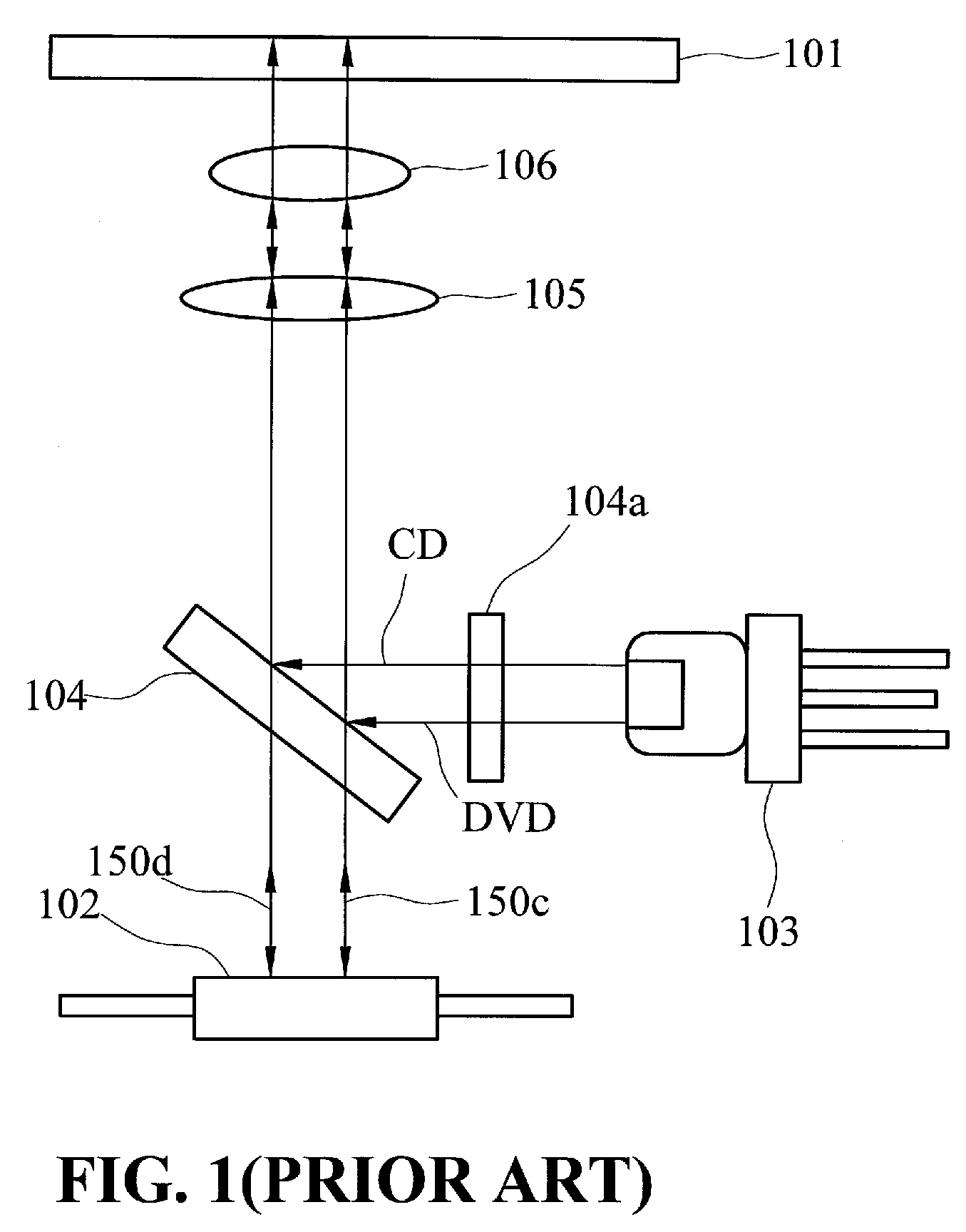
FIELD OF THE INVENTION[0001]The present invention generally relates to a structure for optical pickup head, and more specifically to a structure for optical pickup head having a 10%-30% low reflectivity beam-splitter and moreover an optical signal detector with a 3° to 15° tilt to optical axis to reduce the laser feedback light.BACKGROUND OF THE INVENTION[0002]The compact disc (CD), video compact disc (VCD) and digital versatile disc (DVD), High Density-DVD (HD-DVD) and BD-DVD are widely used in offices and households for information and / or entertainment. Therefore, the industry has been researching to develop more efficient optical pickup technology to improve the quality of the recording media, such as CD, VCD, DVD, HD-DVD and BD-DVD.[0003]An optical pickup head reads or writes data on the recording media. In general, an optical pickup head employs a laser diode (LD) to emit an optical beam through an optical element set to focus on the surface of the recording media. An optical s...

Claims


Application Information

Patent Timeline
IPC IPC(8): G11B7/00
CPCG11B7/1275G11B7/1395G11B7/1381
Inventor WANG, JINN-KANGYANG, TSUNG-MINLIU, CHIN-SUNG
Owner TOPRAY MEMS
Learn More