Fuel Cell Apparatus

a fuel cell and apparatus technology, applied in the direction of chemistry apparatus and processes, electrically generating generators, sustainable buildings, etc., can solve the problems of fuel cell deterioration, easy precipitation, and rapid increase of target gas (raw fuel) supplied to the reforming portion, and achieve the effect of efficient starting

Inactive Publication Date: 2011-03-03
KYOCERA CORP
View PDF3 Cites 30 Cited by
  • Summary
  • Abstract
  • Description
  • Claims
  • Application Information

AI Technical Summary

Benefits of technology

[0011]Accordingly, an object of the present invention is to provide a fuel cell apparatus in which the reforming reaction in the reforming portion can be controlled (changed) at the starting time of the apparatus according to the temperatures of the reforming portion and the vaporizing portion at the starting time of the apparatus so that the fuel cell apparatus can efficiently start while the reforming catalyst can be less likely to deteriorate.

Problems solved by technology

Unfortunately, if the temperature of the reforming portion of a fuel cell apparatus controlled to perform reforming reaction in the order of partial oxidation reforming, autothermal reforming and steam reforming is a predetermined value or more when the fuel cell restarts, the reforming target gas (raw fuel) supplied to the reforming portion may be rapidly increased.
Accordingly, carbon, a constituent of the reforming target gas, may be easily precipitated, and, consequently the fuel cells may deteriorate.
In addition, ignition for burning the fuel gas and unreacted gas (reforming target gas) in one end side of the fuel cells may become difficult.
Also, if partial oxidation reforming is performed in the reforming portion having a predetermined temperature or more at the starting time of the fuel cell apparatus, the reforming portion may easily come to high temperature.
Such a condition may easily cause the reforming catalyst to deteriorate and its lifetime to decrease.

Method used


Image

  • Fuel Cell Apparatus
  • Fuel Cell Apparatus
  • Fuel Cell Apparatus

Examples


Embodiment Construction

[0019]Preferred embodiments of the present invention will now be described in detail with reference to the drawings.

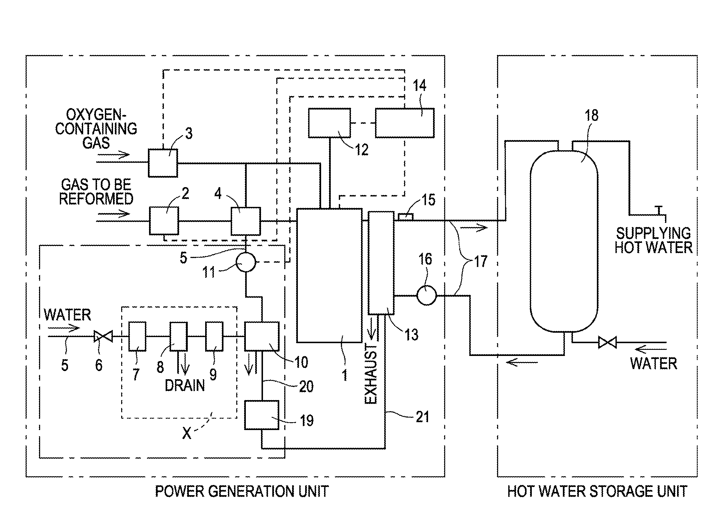
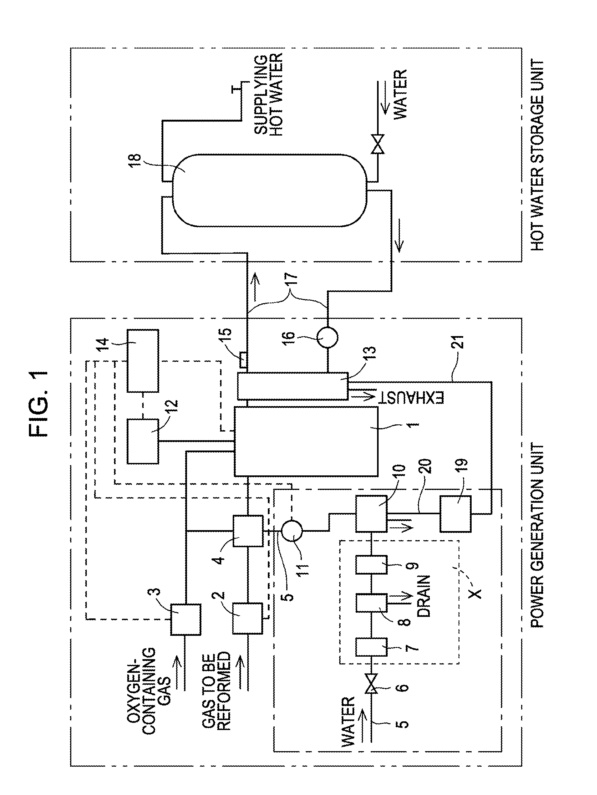
[0020]FIG. 1 is a block diagram of a fuel cell system comprising a fuel cell apparatus according to the present invention. The fuel cell system comprises a power generation unit generating electric power, which is the fuel cell apparatus of the present invention, a hot water storage unit in which heat-exchanged hot water is stored, and circulation piping through which water circulates between these units.

[0021]The fuel cell apparatus shown in FIG. 1 comprises a reforming target gas supply portion 2 supplying a raw fuel, such as natural gas or kerosene (corresponding to the reforming target gas if natural gas is used), a reformer 4 integrally comprising a reforming portion comprising a reforming catalyst for reforming the reforming target gas and a vaporizing portion generating steam to be supplied to the reforming portion, and an oxygen-containing gas supply portion 3 ...


PUM

PropertyMeasurementUnit
temperatureaaaaaaaaaa

Abstract

A fuel cell apparatus comprises a cell stack, a reforming portion (reforming catalyst), a vaporizing portion, a reforming target gas supply, an oxygen-containing gas supply, a water supply, and a controller. The cell stack comprises a plurality of fuel cells electrically connected in series in a housing case. The reforming portion is disposed over the cell stack and is to be exposed to a gas produced by burning a fuel gas from the fuel cells. The reforming catalyst can perform partial oxidation reforming, autothermal reforming and steam reforming as a reforming reaction. The vaporizing portion generates steam to be supplied to the reforming portion. The reforming target gas supply supplies a reforming target gas to the reforming portion. The oxygen gas supply supplies an oxygen gas to the reforming portion. The water supply supplies water to the vaporizing portion. The controller controls the reforming reaction in the reforming portion.

Description

CROSS REFERENCE TO RELATED APPLICATIONS[0001]This application is the U.S. National Stage application of PCT application PCT / JP2008 / 065047 filed on Aug. 22, 2008, which claims priority under 35 U.S.C. §119 to Japanese Patent Application No. 2007-222980 filed on Aug. 29, 2007, and the contents of each of these applications are incorporated herein by reference in their entirety.FIELD OF THE INVENTION[0002]The present invention relates to fuel cell apparatuses, particularly to a fuel cell apparatus that can be efficiently started.BACKGROUND[0003]Fuel cell apparatuses and their operation methods have recently been proposed for next-generation energy. Fuel cells can generate electric power, using a fuel gas (hydrogen-containing gas) and an oxygen-containing gas (normally air), and the fuel cell apparatus comprises the fuel cell and auxiliary devices operating the fuel cell within an enclosure. For example, a fuel cell apparatus has been proposed which comprises within a housing case a cel...

Claims


Application Information

Patent Timeline
Patent Type & Authority Applications(United States)
IPC IPC(8): H01M8/06
CPCC01B3/382H01M8/0606C01B2203/0244C01B2203/0261C01B2203/066C01B2203/1294C01B2203/1604C01B2203/1619C01B2203/169H01M8/04223H01M8/04373H01M8/04776H01M8/0618H01M2250/405Y02E60/50Y02B90/16C01B2203/0233Y02B90/10H01M8/04302H01M8/04225H01M8/2432
Inventor TAKAHASHI, NARUTO
Owner KYOCERA CORP
Why Eureka
Try Eureka