
Stent with variable cross section braiding filament and method for making same

Inactive Publication Date: 2011-03-03
STRYKER EURO OPERATIONS HLDG LLC +1
View PDF9 Cites 95 Cited by
  • Summary
  • Abstract
  • Description
  • Claims
  • Application Information

AI Technical Summary

Benefits of technology

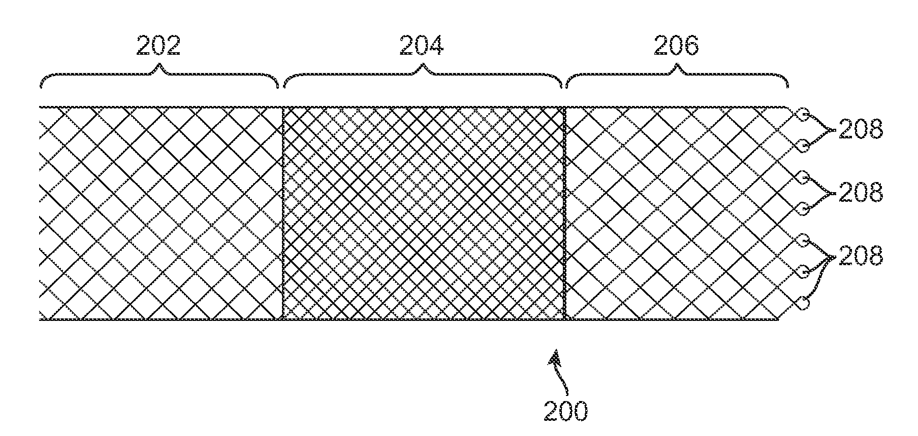
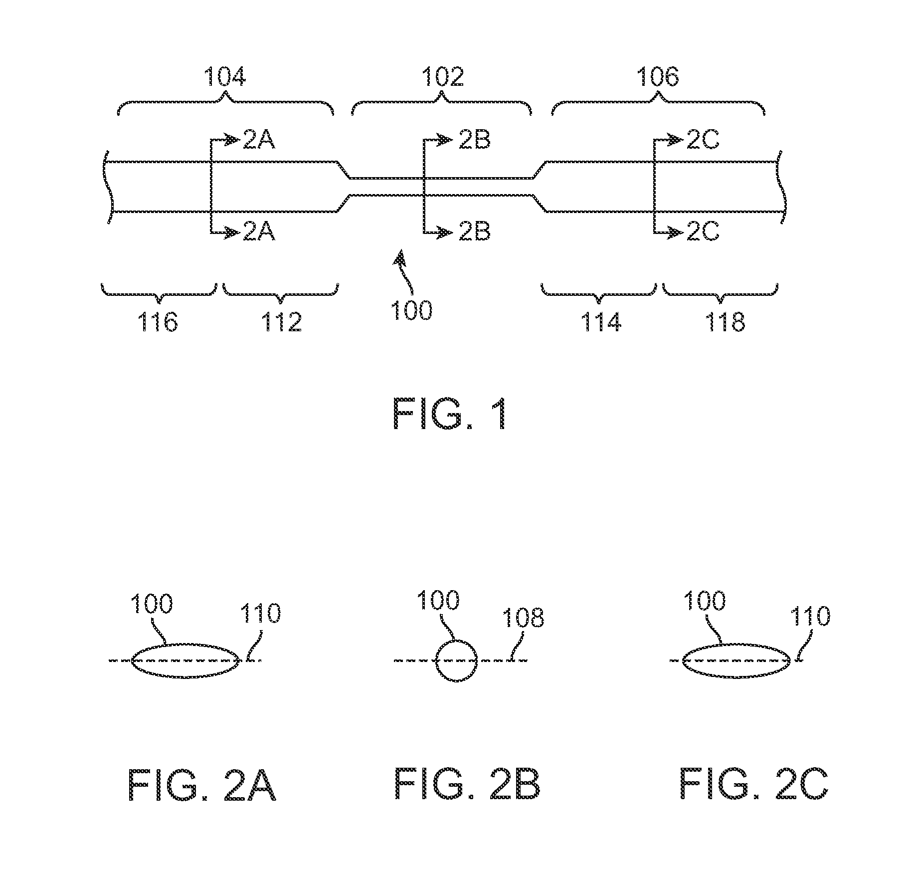
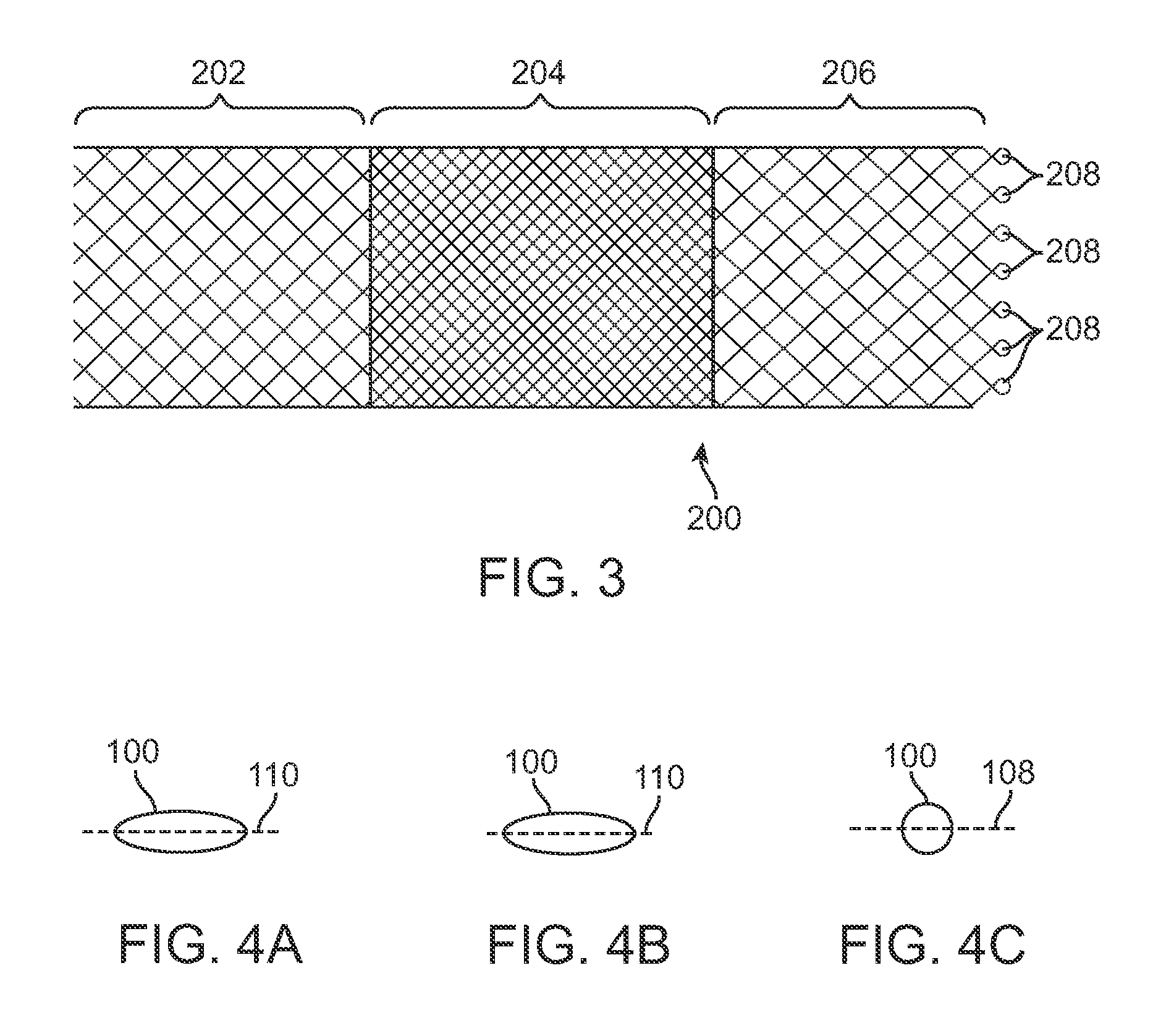
[0013]In accordance with a general aspect of the inventions disclosed herein, a braided stent is formed from a filament having at least one circular zone and at least two non-circular zones. Embodiments of the braided stent may have a proximal segment, a middle segment, and a distal segment. In one such embodiment, a porosity of the middle segment is lower than a respective poros

Problems solved by technology

Perceived problems with current stents include increasing radial stiffness with decreasing porosity by increasing picks per inch.
Stents have been braided with ribbons instead of wire with a circular cross section to decrease porosity without an undue increase in radial stiffness, but such stents have unacceptably low radial pressure at the anchoring ends.
Further, such stents do not form desirable looped end designs well, because it is challenging to maintain the ribbon in a single plane while forming a loop.
Another perceived problem with current stents is that braiding stents from either ribbon or wire with a circular cross section results in limited porosity gradient between ends, where high porosity is desirable, and the middle, where low porosity is desirable.

Method used


Image

  • Stent with variable cross section braiding filament and method for making same
  • Stent with variable cross section braiding filament and method for making same
  • Stent with variable cross section braiding filament and method for making same

Examples


Embodiment Construction

[0030]FIG. 1 illustrates a stent filament 100 according to an embodiment of the invention. The filament 100 may be formed from both metallic and non-metallic materials.

[0031]Metallic filament materials include, without limitation, nitinol, stainless steel, cobalt-based alloy such as Elgiloy, platinum, gold, titanium, tantalum, niobium, and combinations thereof and other biocompatible materials, as well as polymeric materials. The filament 100 or zones thereof may have an inner core of tantalum, gold, platinum, iridium or combinations thereof and an outer member or layer of nitinol to provide a composite filament for improved radiopacity or visibility. Non-metallic materials include, without limitation, polyesters, such as polyethylene terephthalate (PET) polyesters, polypropylenes, polyethylenes, polyurethanes, polyolefins, polyvinyls, polymethylacetates, polyamides, naphthalane dicarboxylene derivatives, natural silk, and polytetrafluoroethylenes. Non-metallic materials also includ...


PUM


Abstract

A braided stent comprises a filament having at least one circular zone and at least two non-circular zones. Embodiments of the braided stent have a proximal segment, a middle segment, and a distal segment, wherein a porosity of the middle segment is lower than, a respective porosity of the proximal and distal segments. In one embodiment, a radial pressure of the middle segment is separately controlled to be different from, e.g., less than, a radial pressure of the distal segment. In another embodiment, a stiffness of the middle segment is separately controlled to be different from, e.g., less than, a stiffness of the distal segment.

Description

RELATED APPLICATION DATA[0001]This application claims the benefit under 35 U.S.C. §119 to provisional application Ser. No. 61 / 237,431, filed Aug. 27, 2009, which is incorporated by reference into the present application in its entirety.FIELD OF THE INVENTION[0002]The field of the invention generally relates to devices, such as stents, for reinforcing the structural integrity of vessels of a human or veterinary patient. More particularly, the field of the invention relates to stents with variable porosity.BACKGROUND OF THE INVENTION[0003]Stents, grafts, stent-grafts, vena cava filters and similar implantable medical devices, collectively referred to hereinafter as stents, are radially expandable endoprostheses which are typically intravascular implants capable of being implanted transluminally and enlarged radially after being introduced percutaneously. Stents may be implanted in a variety of body lumens or vessels such as within the vascular system, urinary tracts, bile ducts, etc. ...

Claims


Application Information

Patent Timeline
IPC IPC(8): A61F2/82D04C1/00A61F2/90
CPCA61F2/90A61F2002/823A61F2250/0015A61F2210/0076A61F2250/0036A61F2250/0039A61F2250/0018
Inventor BASHIRI, MEHRANBAHREINIAN, LEILA
Owner STRYKER EURO OPERATIONS HLDG LLC
Learn More