Fenestrated prosthesis

US20110054594A1Active Publication Date: 2011-03-03ENDOLOGIX LLC +1

Image

  • Fenestrated prosthesis
  • Fenestrated prosthesis
  • Fenestrated prosthesis

Examples


Embodiment Construction

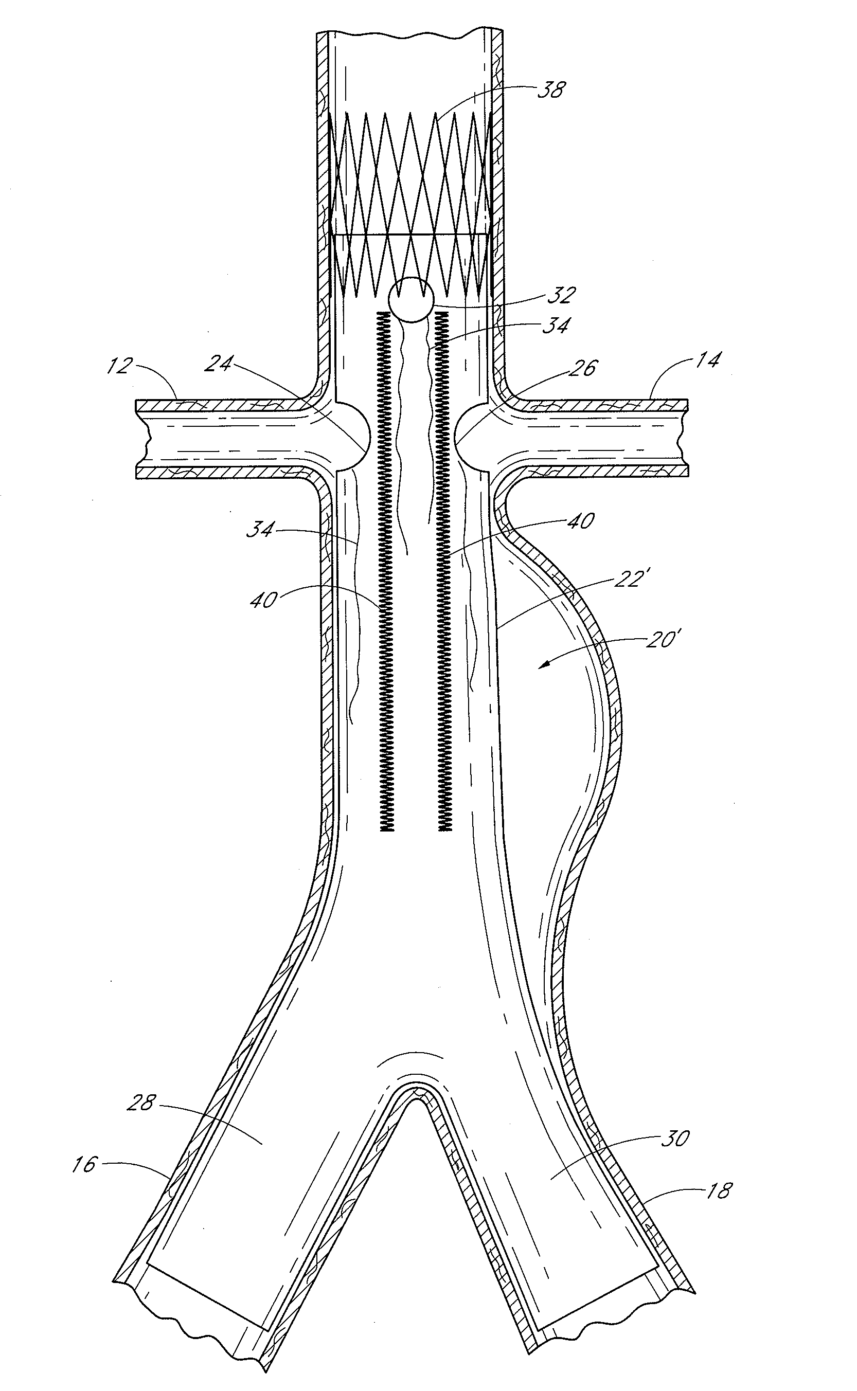
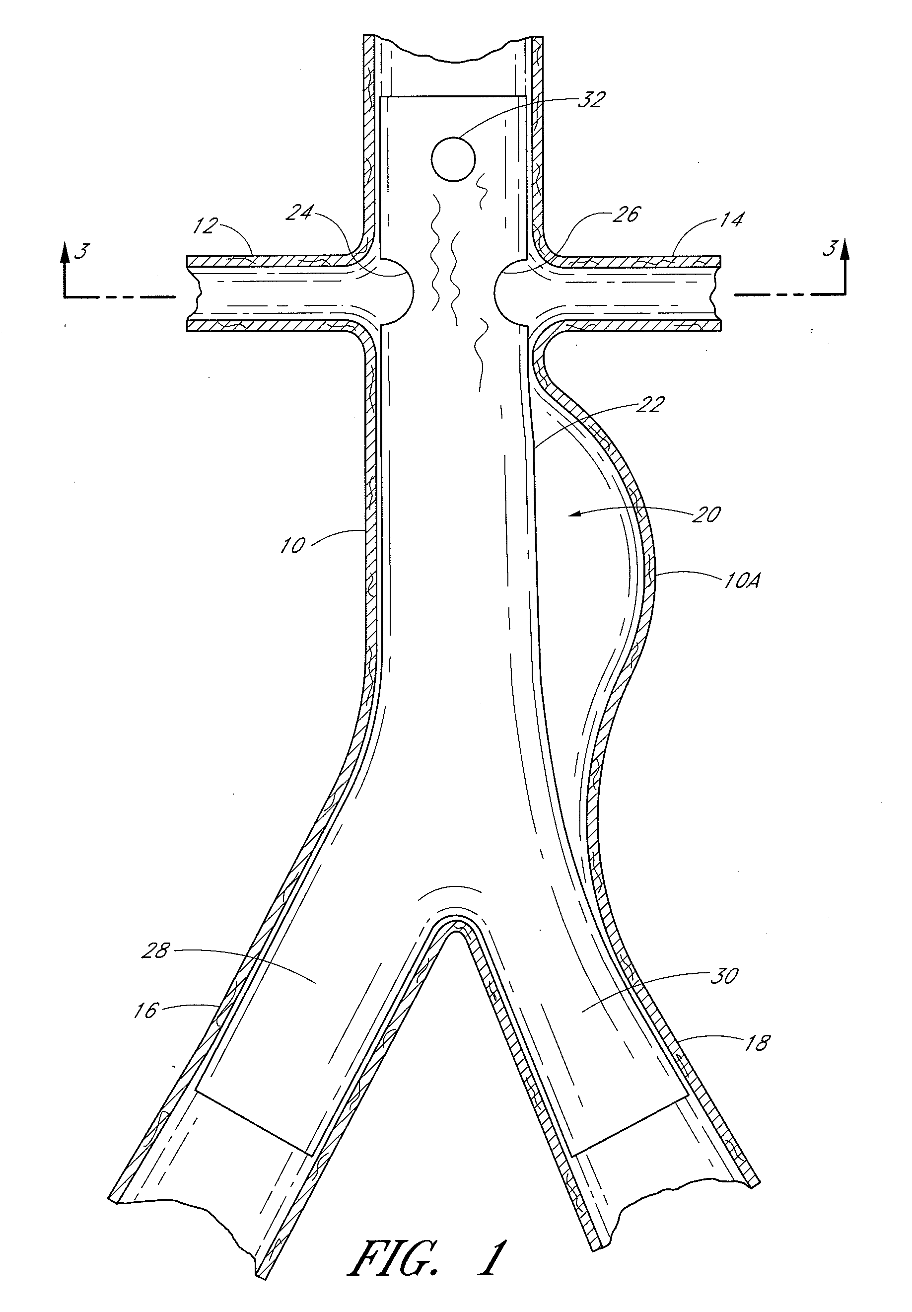
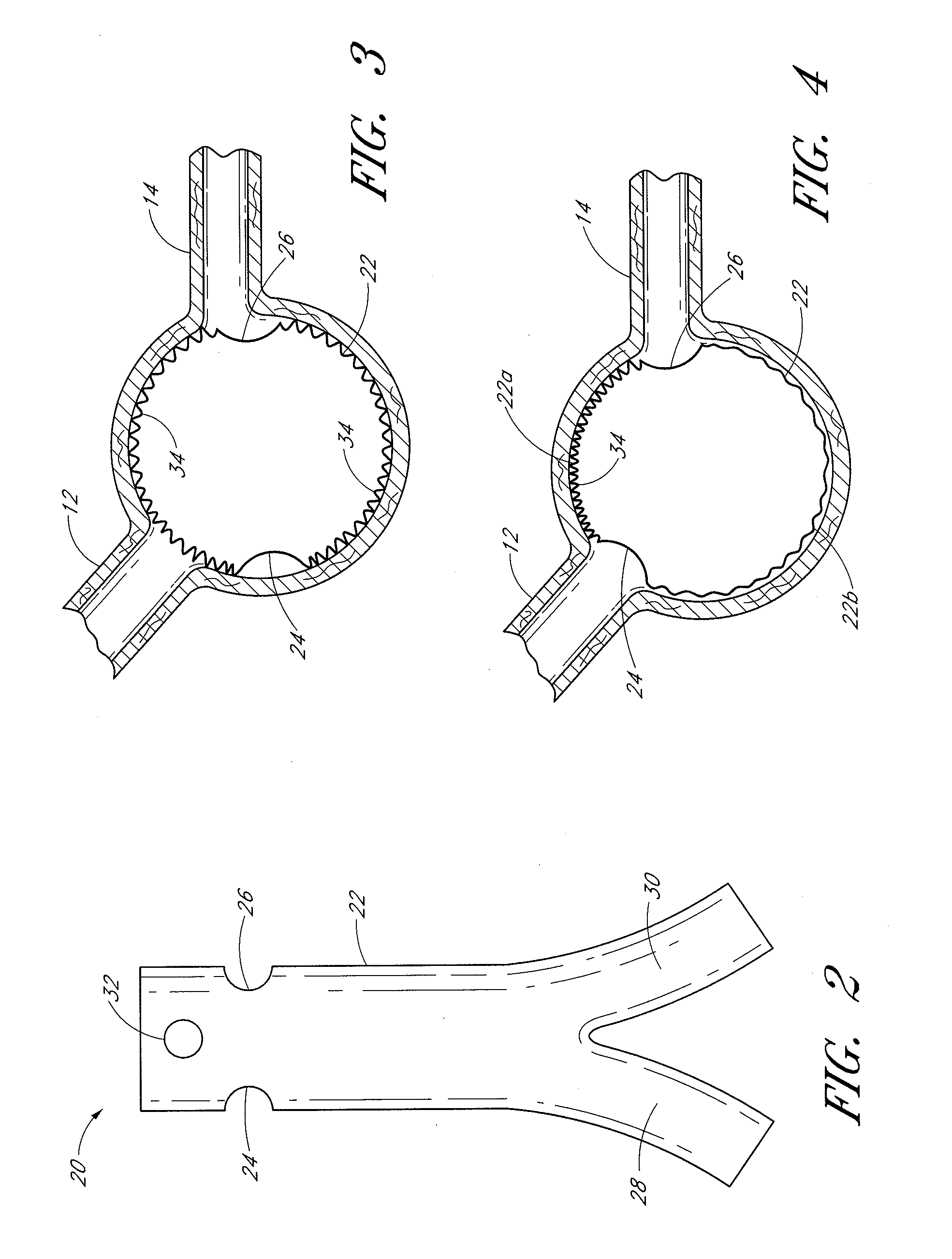
[0016]Some embodiments of the endoluminal prostheses disclosed (directly and / or by incorporation by reference) herein pertain to designs and methods of placement of a branch graft or branch graft system having lateral openings in the main graft. The main graft can be positioned within the main blood vessel such as the aorta so that the lateral openings (also referred to herein as fenestrations) can be aligned with the branch blood vessels, to allow blood to flow through the openings in the main graft and into the branch vessels. Because the axial and angular position of the branch blood vessels can vary from one patient's anatomy to the next, the embodiments of the graft systems disclosed herein can allow a surgeon to adjust the position of the fenestrations so as to align the fenestrations with the branch vessels so that blood flow through the branch vessels is not obstructed by the main graft.

[0017]The branch graft system can comprise a tubular expandable main body and at least on...


PUM

PropertyMeasurementUnit
Fractionaaaaaaaaaa
Fractionaaaaaaaaaa
Angleaaaaaaaaaa

Abstract

Some embodiments of the present disclosure are directed to endoluminal prostheses having one or more reinforced fenestrations therein. The one or more reinforced fenestrations can have improved sealing capabilities with respect to branch grafts deployed within the fenestrations, improved tear resistance and expandability, and improved pull-out resistance for branch grafts. In some embodiments, the endoluminal prosthesis can have a main graft body defining a flow lumen therethrough, a first opening passing through a wall of the main graft body, and a first support member supported by the main graft body and overlapping an edge of the first opening, the first support member being configured to at least increase the tear resistance of the main graft body adjacent to the first opening. The support member can be stitched or otherwise attached to the main graft adjacent to the fenestration.

Description

PRIORITY INFORMATION AND INCORPORATION BY REFERENCE[0001]This application claims priority benefit under 35 U.S.C. §119(e) of Provisional Application 61 / 173,485 filed Apr. 28, 2009, Provisional Application 61 / 228,048 filed Jul. 23, 2009, and Provisional Application 61 / 231,898 filed Aug. 6, 2009, which applications are hereby incorporated by reference as if fully set forth herein. Additionally, U.S. patent application Ser. No. 12 / 496,446, filed on Jul. 1, 2009 (entitled ā€œCATHETER SYSTEM AND METHODS OF USING SAMEā€), U.S. patent application Ser. No. 12 / 390,346, filed on Feb. 20, 2009 (entitled ā€œDESIGN AND METHOD OF PLACEMENT OF A GRAFT OR GRAFT SYSTEMā€), U.S. patent application Ser. No. 12 / 101,863, filed on Apr. 11, 2008 (entitled ā€œBIFURCATED GRAFT DEPLOYMENT SYSTEMS AND METHODSā€), U.S. Pat. No. 6,077,296, filed on Mar. 4, 1998 (entitled ā€œENDOLUMINAL VASCULAR PROSTHESISā€), U.S. Pat. No. 6,953,475, filed on Sep. 30, 2003 (entitled ā€œBIFURCATION GRAFT DEPLOYMENT CATHETERā€), and U.S. Pat. N...

Claims


Application Information

Patent Timeline
03 Mar 2011
Publication
US20110054594A1
IPC
A61F2/82; B23P11/02; A61F2/06
CPC
A61F2/07; A61F2/954; A61F2/966; A61F2002/061; A61F2002/065; Y10T29/49863; A61F2002/9511; A61F2250/0039
Inventors
MAYBERRY, KEVIN; CLAIR, DANIEL