Method of manufacturing radiation detector

a radiation detector and manufacturing method technology, applied in the direction of instruments, x/gamma/cosmic radiation measurement, synthetic resin layered products, etc., can solve the problem of manufacturing the conventional radiation detector and achieve the effect of accurate joining

Inactive Publication Date: 2011-03-10
SHIMADZU CORP
View PDF5 Cites 10 Cited by
  • Summary
  • Abstract
  • Description
  • Claims
  • Application Information

AI Technical Summary

Benefits of technology

[0030]According to this invention, the method of manufacturing the radiation detector may be provided in which the step of hardening the hardening resin and the step of optically coupling the scintillator and the light guide are performed en bloc. Here, both steps of manufacturing the scintillator and the light guide include the step of hardening the hardening resin. Giving attention to this, this invention has no configuration of optically coupling the light guide and the scintillator after manufacturing independently the light guide or the scintillator. Instead of this configuration, this invention has a configuration of manufacturing either the light guide or the scintillator and then placing either the manufactured light guide or the scintillator on the incomplete scintillator or light guide. Such configuration allows one surface of the light guide or the scintillator to be penetrated with the hardening resin prior to hardening. When the hardening resin hardens under this state, the hardening resin that penetrates the one surface of the light guide or the scintillator is to harden, which results in joining of the light guide and the scintillator.
[0031]As noted above, the method of manufacturing the radiation detector may be provided in which the step of hardening the hardening resin to manufacture the scintillator or the light guide and the step of optically coupling the scintillator and the light guide are performed en bloc. Accordingly, the radiation detector may be manufactured with no complicated process of forming the scintillator and the light guide individually and coupling them with the optical adhesive.

Problems solved by technology

However, the method of manufacturing the conventional radiation detector has the following drawbacks.
That is, the problem is that the method of manufacturing the conventional radiation detector has many numbers of processes, and thus is complicated.

Method used


Image

  • Method of manufacturing radiation detector
  • Method of manufacturing radiation detector
  • Method of manufacturing radiation detector

Examples


embodiment 1

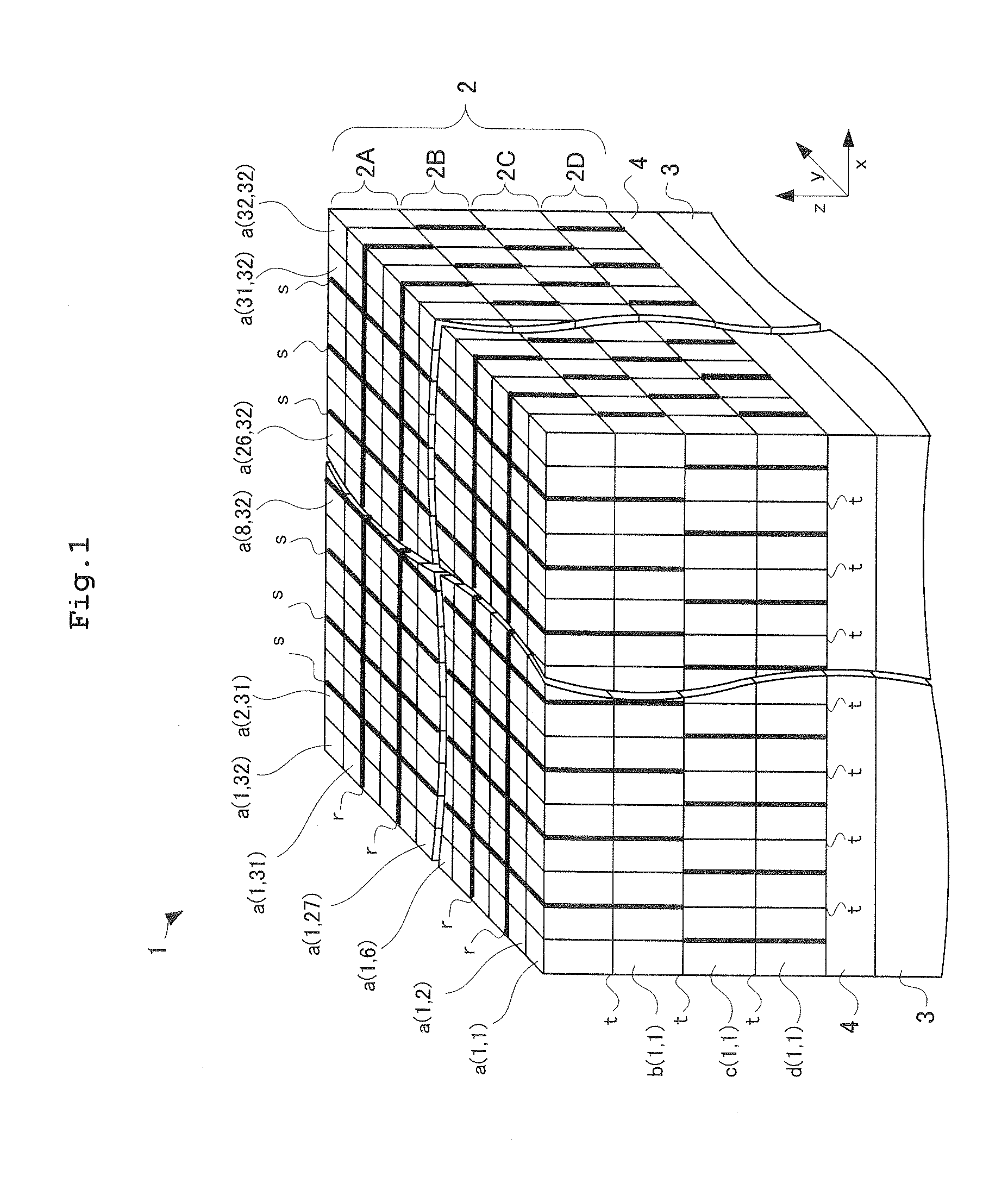
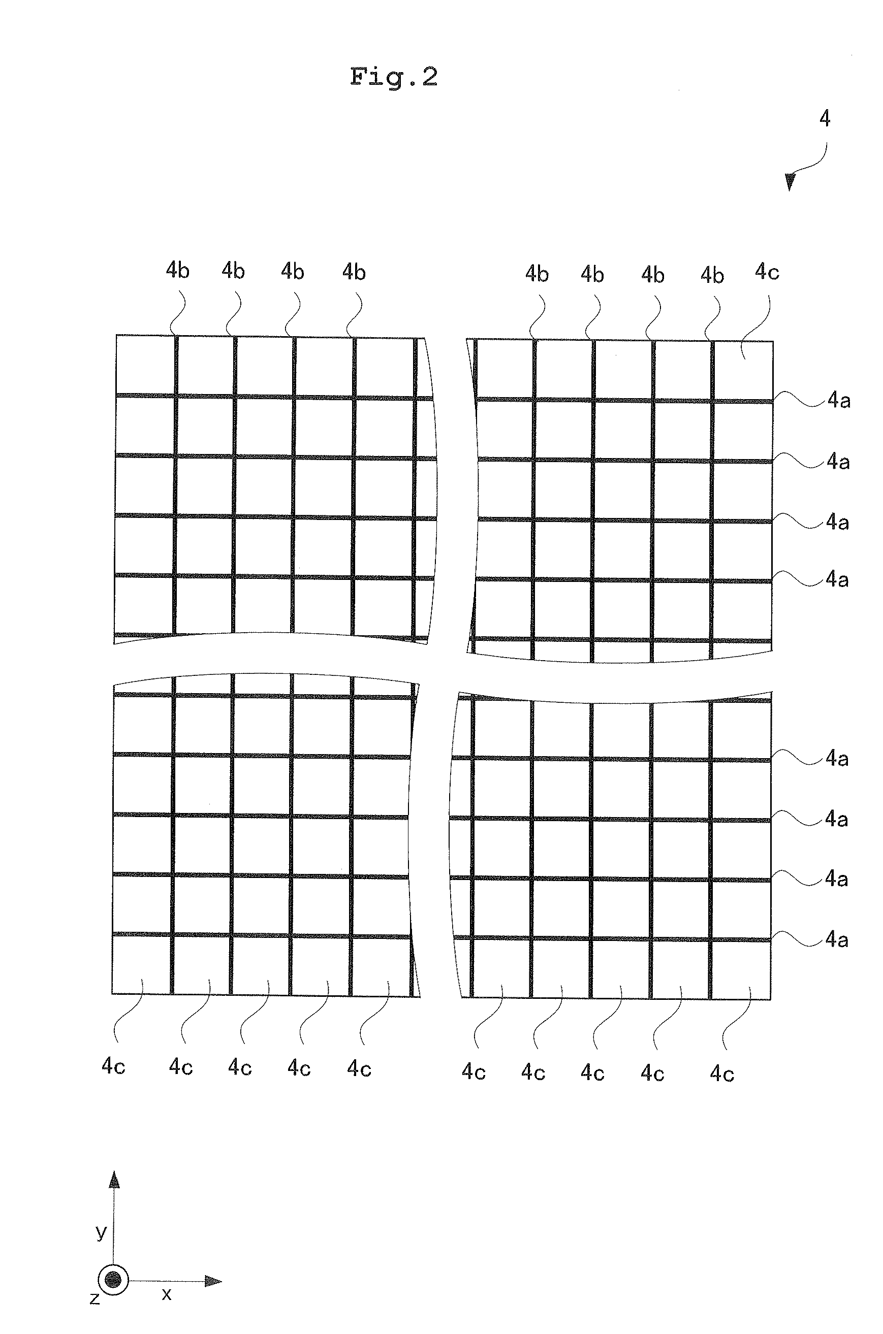
[0065]Prior to description of a method of manufacturing a radiation detector according to Embodiment 1, a configuration is to be described of a radiation detector 1 according to Embodiment 1. FIG. 1 is a perspective view of the radiation detector according to Embodiment 1. As shown in FIG. 1, the radiation detector 1 according to Embodiment 1 includes a scintillator 2 that is formed of scintillation counter crystal layers each laminated in order of a scintillation counter crystal layer 2D, a scintillation counter crystal layer 2C, a scintillation counter crystal layer 2B, and a scintillation counter crystal layer 2A, in turn, in a z-direction, a photomultiplier tube (hereinafter referred to as a light detector) 3 having a function of position discrimination that is provided on an undersurface of the scintillator 2 for detecting fluorescence emitted from the scintillator 2 for receiving fluorescence, and a light guide 4 arranged between the scintillator 2 and the light detector 3. Co...

embodiment 2

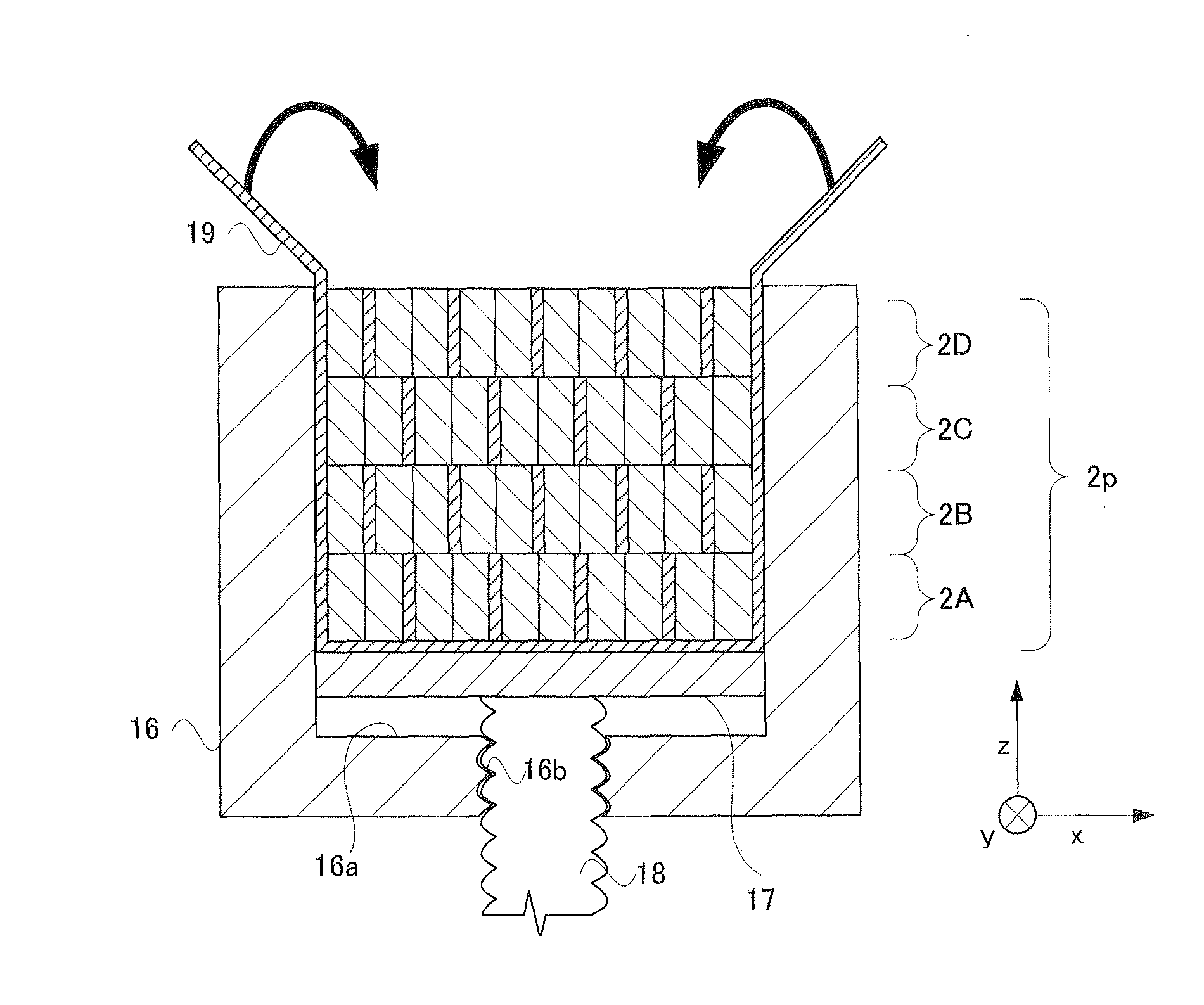
[0109]Next, description will be given of a configuration in Embodiment 2. Embodiment 2 differs from Embodiment 1 in manufacturing in advance of the scintillator 2. FIG. 22 is a flow chart showing a method of manufacturing a radiation detector according to Embodiment 2. The configuration of Embodiment 2 includes the step of manufacturing the scintillator. The same steps proceed as the step S5 of manufacturing the temporary assembly and the step S6 of pouring the second hardening resin in Embodiment 1 upon manufacturing of this scintillator. Thus, the explanation thereof is to be omitted. In Embodiment 2, at the time the temporary assembly 2p is placed in the receptacle for joint 20, the optical adhesive 21 (the second hardening resin) hardens, and the scintillator 2 having the scintillation counter crystals 11 joined to one another is removed from the receptacle for joint 20. This unique step in Embodiment 2 is referred to as the step T1 of joining the scintillation counter crystals....


PUM

PropertyMeasurementUnit
thicknessaaaaaaaaaa
heightaaaaaaaaaa
widthaaaaaaaaaa

Abstract

With this invention, a light guide is placed on a scintillator while an optical adhesive for forming the scintillator does not harden. Accordingly, a method of manufacturing a radiation detector may be provided in which the step of hardening the optical adhesive that joins scintillation counter crystals to one another and the step of optically coupling the scintillator and the light guide are performed en bloc. Accordingly, the radiation detector may be manufactured with no complicated process of forming the scintillator and the light guide individually and coupling them with the optical adhesive.

Description

TECHNICAL FIELD [0001]This invention relates to a method of manufacturing a radiation detector having a scintillator, a light guide, and a light detector that are optically coupled to one another in turn.BACKGROUND ART [0002]In medical fields, emission computed tomography (ECT: Emission Computed Tomography) apparatus is used that detects radiation (such as gamma rays) emitted from radiopharmaceutical that is administered to a subject and is localized to a site of interest for obtaining sectional images of the site of interest in the subject showing radiopharmaceutical distributions. Typical ECT apparatus includes, for example, a PET (Positron Emission Tomography) device and an SPECT (Single Photon Emission Computed Tomography) device.[0003]A PET device will be described by way of example. The PET device has a radiation detector ring with block radiation detectors arranged in a ring shape. The detector ring is provided for surrounding a subject, and allows detection of radiation that...

Claims


Application Information

Patent Timeline
Patent Type & Authority Applications(United States)
IPC IPC(8): B32B37/24
CPCG01T1/2018G01T1/20185
Inventor TONAMI, HIROMICHI
Owner SHIMADZU CORP
Why Eureka
Try Eureka