Control system and method for remotely isolating powered units in a rail vehicle system

a technology of control system and power system, which is applied in the direction of reciprocating combination engine, process and machine control, instruments, etc., can solve the problems of not being able to remotely turn on or off the electrical power system of remote powered units, the operator of these powered rail vehicle systems may change the required tractive effort, and the locomotive cannot remotely control the power system

Active Publication Date: 2011-03-10
GE GLOBAL SOURCING LLC
View PDF27 Cites 54 Cited by
  • Summary
  • Abstract
  • Description
  • Claims
  • Application Information

AI Technical Summary

Benefits of technology

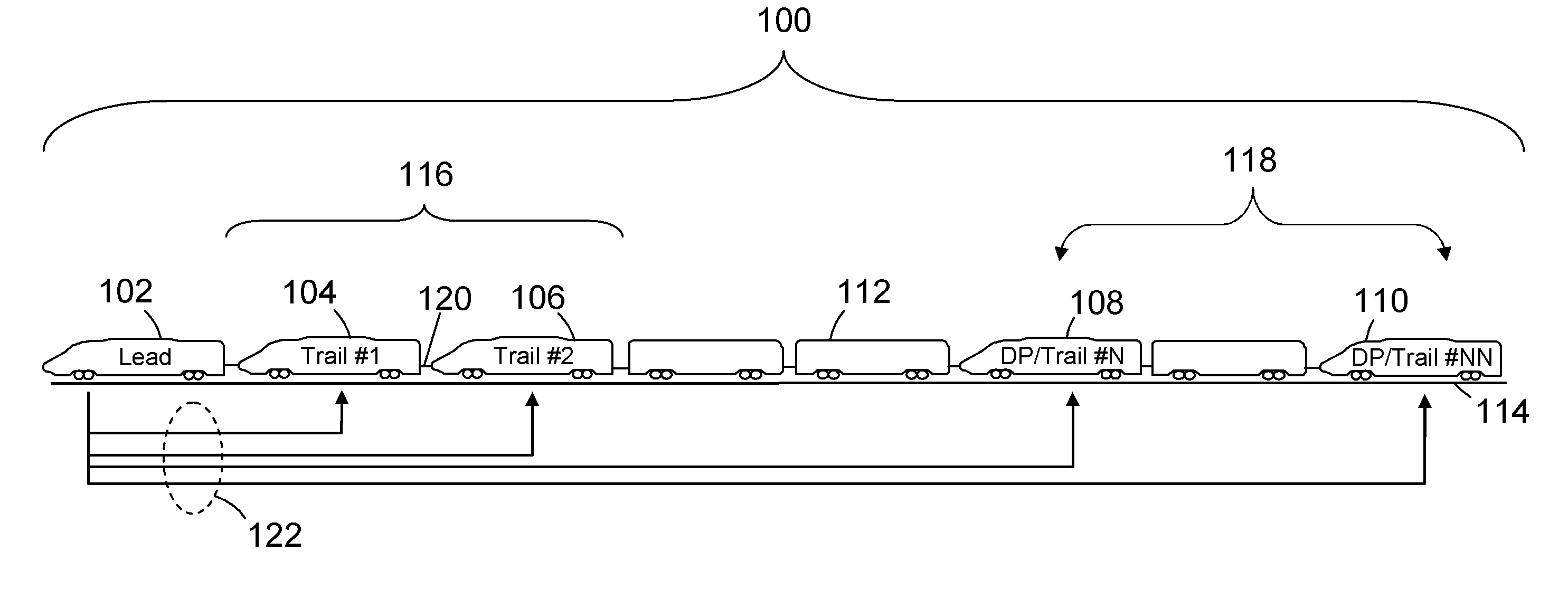
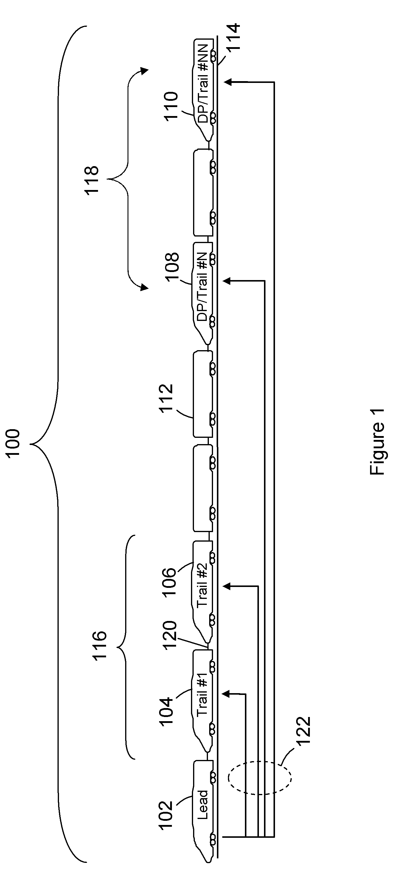
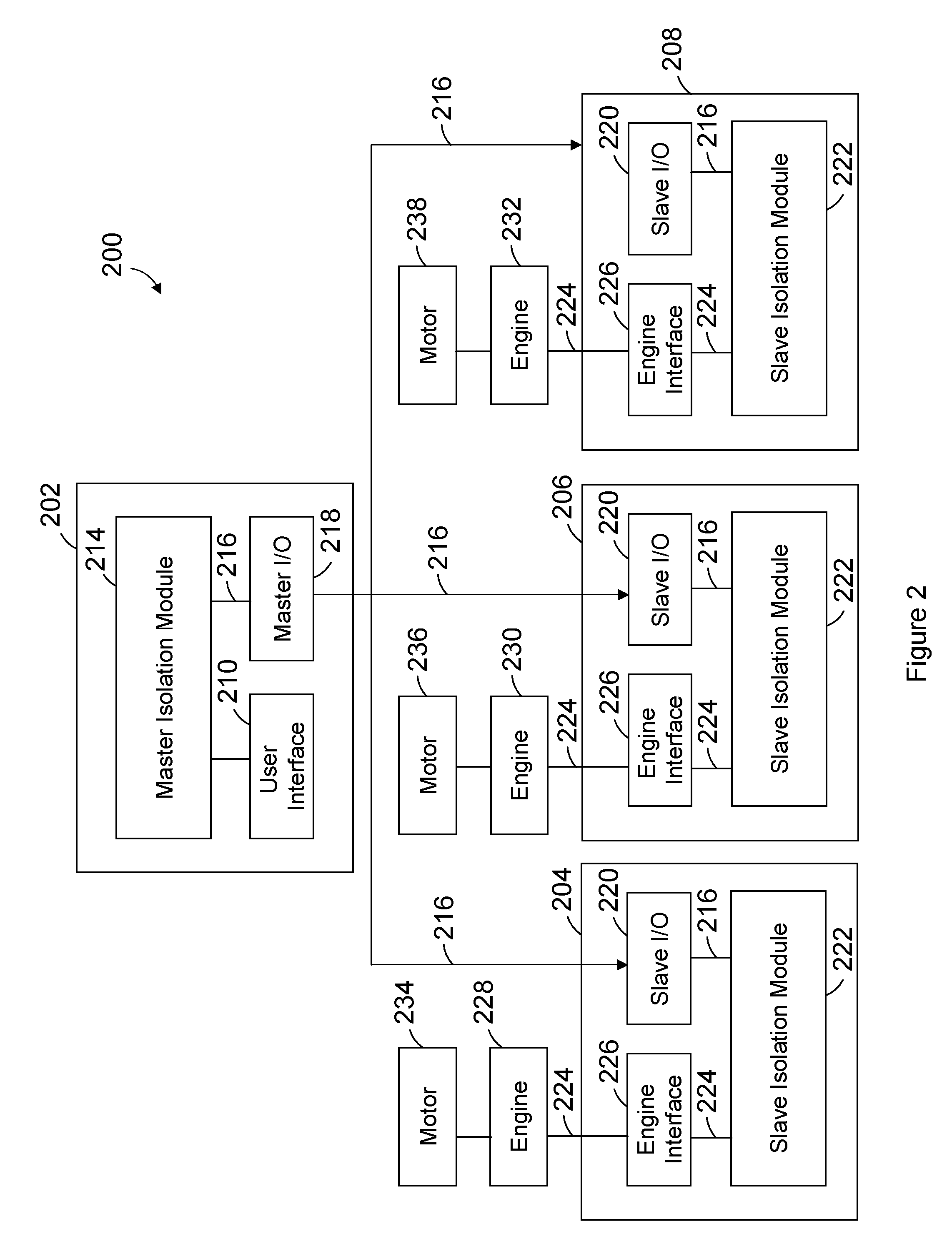
[0006]In one embodiment, a control system for a rail vehicle system including a lead powered unit and a remote powered unit is provided. The system includes a user interface, a master isolation module, and a slave controller. The user interface is disposed in the lead powered unit and is configured to receive an isolation command to turn on or off the remote powered unit. The master isolation module is configured to receive the isolation command from the user interface and to communicate an instr

Problems solved by technology

While the required tractive effort may change during a trip, the operators of these powered rail vehicle systems do not have the ability to remotely turn the electrical power systems of remote powered units on or off during the trip.
For example, an operator in a lead locomotive does not have the ability to remotely turn one or more of the trailing locomotives' electrical power on or off, if the tractive effort required to propel the train changes during

Method used


Image

  • Control system and method for remotely isolating powered units in a rail vehicle system
  • Control system and method for remotely isolating powered units in a rail vehicle system
  • Control system and method for remotely isolating powered units in a rail vehicle system

Examples


Embodiment Construction

[0015]The foregoing summary, as well as the following detailed description of certain embodiments of the present invention, will be better understood when read in conjunction with the appended drawings. To the extent that the figures illustrate diagrams of the functional blocks of various embodiments, the functional blocks are not necessarily indicative of the division between hardware circuitry. Thus, for example, one or more of the functional blocks (for example, processors or memories) may be implemented in a single piece of hardware (for example, a general purpose signal processor, microcontroller, random access memory, hard disk, and the like). Similarly, the programs may be stand alone programs, may be incorporated as subroutines in an operating system, may be functions in an installed software package, and the like. The various embodiments are not limited to the arrangements and instrumentality shown in the drawings.

[0016]As used herein, an element or step recited in the sing...


PUM


Abstract

A control system for a rail vehicle system including a lead powered unit and a remote powered unit is provided. The system includes a user interface, a master isolation module and a slave controller. The user interface is disposed in the lead powered unit and is configured to receive an isolation command to turn on or off the remote powered unit. The master isolation module is configured to receive the isolation command from the user interface and to communicate an instruction based on the isolation command. The slave controller is configured to receive the instruction from the master isolation module. The slave controller causes the remote powered unit to supply tractive force to propel the rail vehicle system when the instruction directs the slave controller to turn on the remote powered unit. The slave controller causes the remote powered unit to withhold the tractive force when the instruction directs the slave controller to turn off the remote powered unit.

Description

BACKGROUND OF THE INVENTION[0001]This invention relates generally to powered rail vehicle systems.[0002]Known powered rail vehicle systems include one or more powered units and, in certain cases, one or more non-powered rail cars. The powered units supply tractive force to propel the powered units and cars. The non-powered cars hold or store goods and / or passengers. (“Non-powered” rail car generally encompasses any rail car without an on-board source of motive power.) For example, some known powered rail vehicle systems include a rail vehicle system (e.g., train) having locomotives and cars for conveying goods and / or passengers along a track. Some known powered rail vehicle systems include several powered units. For example, the systems may include a lead powered unit, such as a lead locomotive, and one or more remote or trailing powered units, such as trailing locomotives, that are located behind and (directly or indirectly) coupled with the lead powered unit. The lead and remote p...

Claims


Application Information

Patent Timeline
IPC IPC(8): G05D1/00B61L3/00G06F17/00
CPCB61C17/12B61L15/0036B61L15/0027B61L3/006
Inventor MELTSER, MIKHAILMEDEMA, TIMOTHYBRAND, JOHNCOOPER, JARED KLINEMANGOODERMUTH, TODDELDREDGE, DAVID ALLENFOY, ROBERTMCNALLY, CHRISTOPHERNOFFSINGER, JOSEPH FORRESTMCKAY, DAVIDLACY, PATRICIASMITH, KRISTOPHER
Owner GE GLOBAL SOURCING LLC
Why Eureka
Try Eureka