Thermal energy conversion method

a technology of thermal energy and heat source, applied in the field of thermodynamics, can solve the problems of inability to capture and recycle heat, complex boiling water at multiple pressures/temperatures to capture heat at multiple temperature levels as heat source stream, etc., and achieve the effect of efficient and effective power generation

Active Publication Date: 2011-03-17
ECHOGEN POWER SYST +1
View PDF26 Cites 36 Cited by
  • Summary
  • Abstract
  • Description
  • Claims
  • Application Information

AI Technical Summary

Problems solved by technology

Other times it is not feasible to capture and recycle this heat because it is either too high in temperature or it may contain insufficient mass flow.
The steam-based Rankine cycle is not always practical because it requires heat source streams that are relatively high in temperature (600° F. or higher) or arc large in overall heat content.
The complexity of boiling water at multiple pressures / temperatures to capture heat at multiple temperature levels as the heat source stream is cooled, is costly in both equipment cost and operating labor.
The steam-based Rankine cycle is not a realistic option for streams of small flow rate and / or low temperature.

Method used


Image

  • Thermal energy conversion method
  • Thermal energy conversion method
  • Thermal energy conversion method

Examples


Embodiment Construction

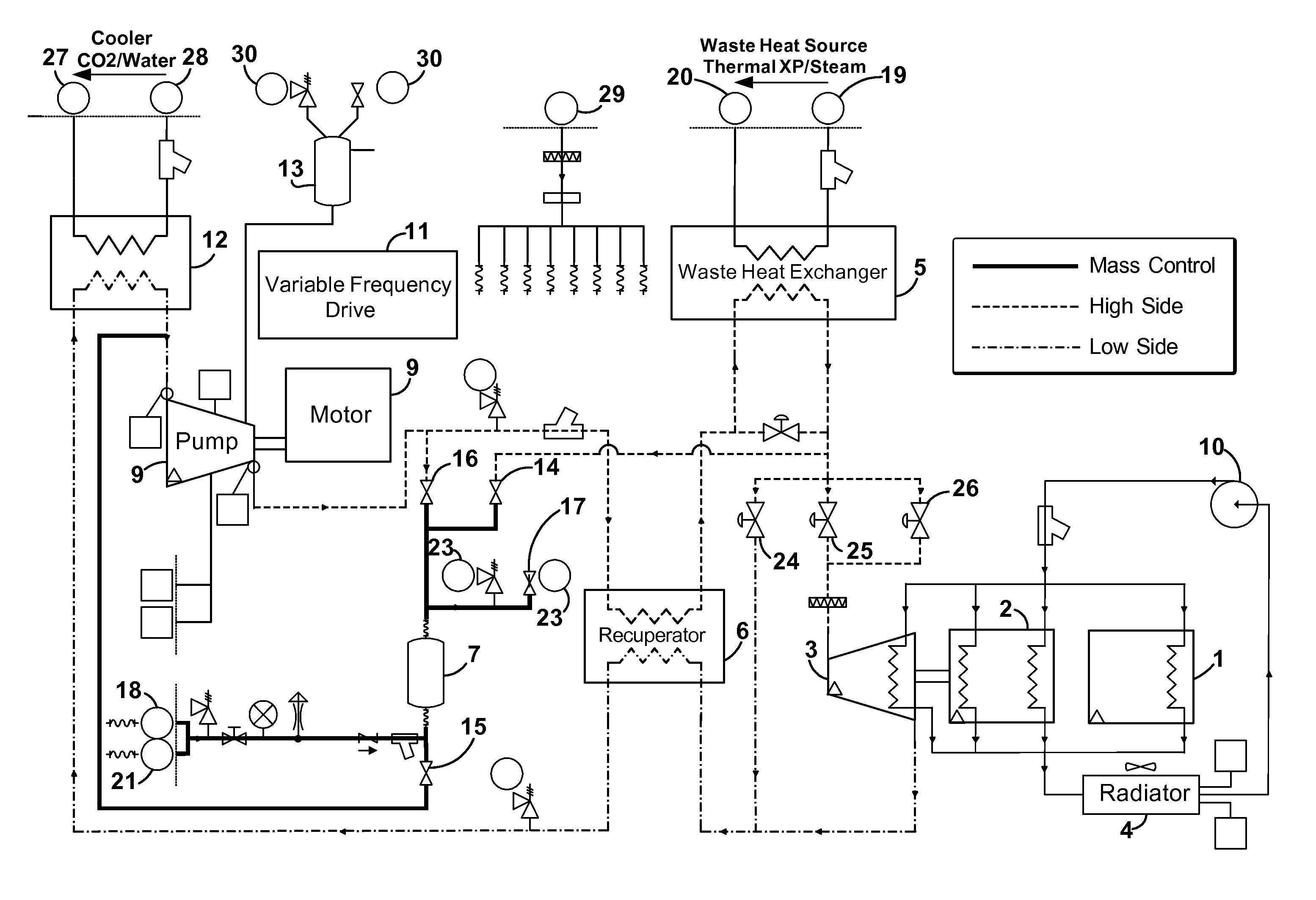
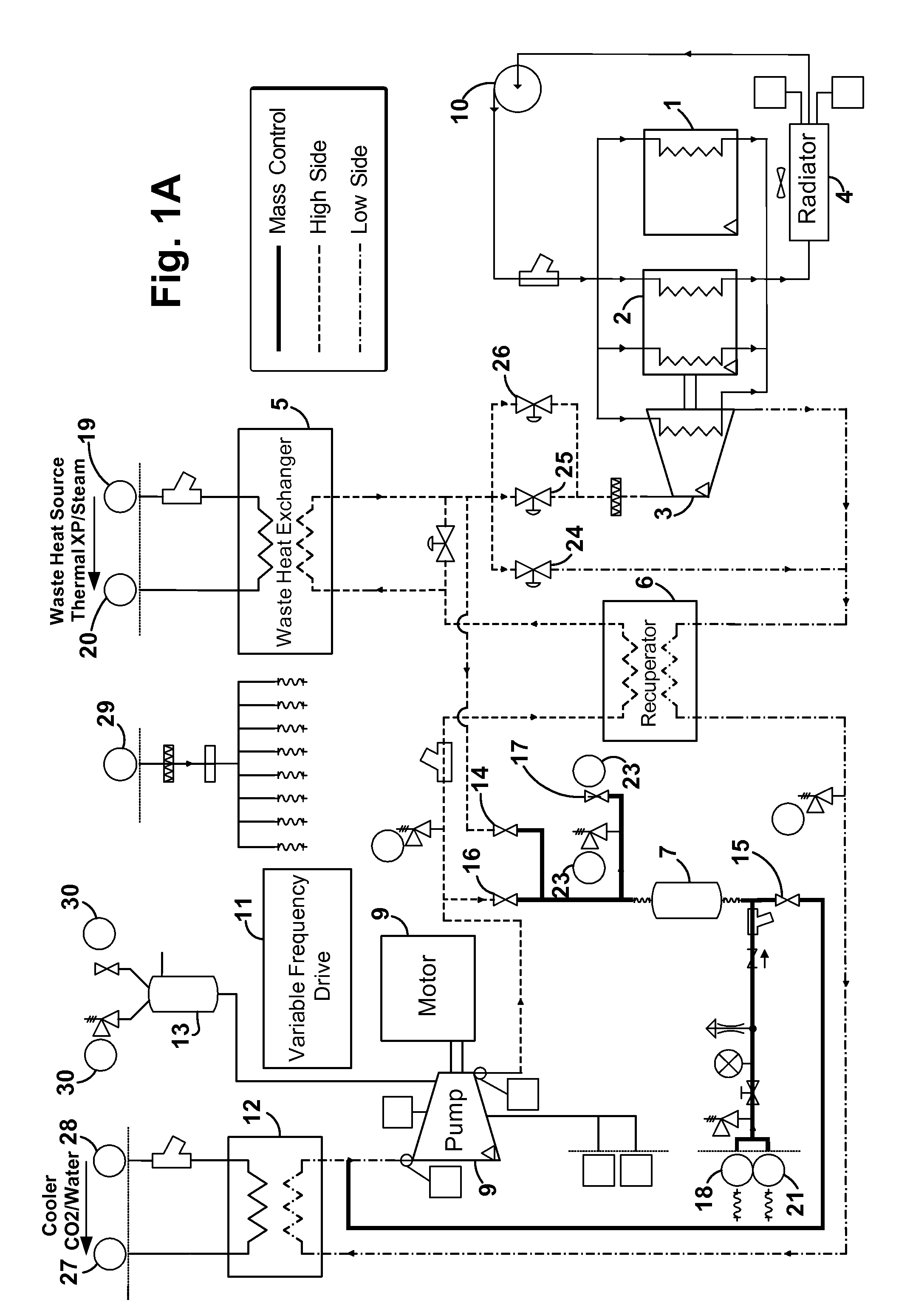
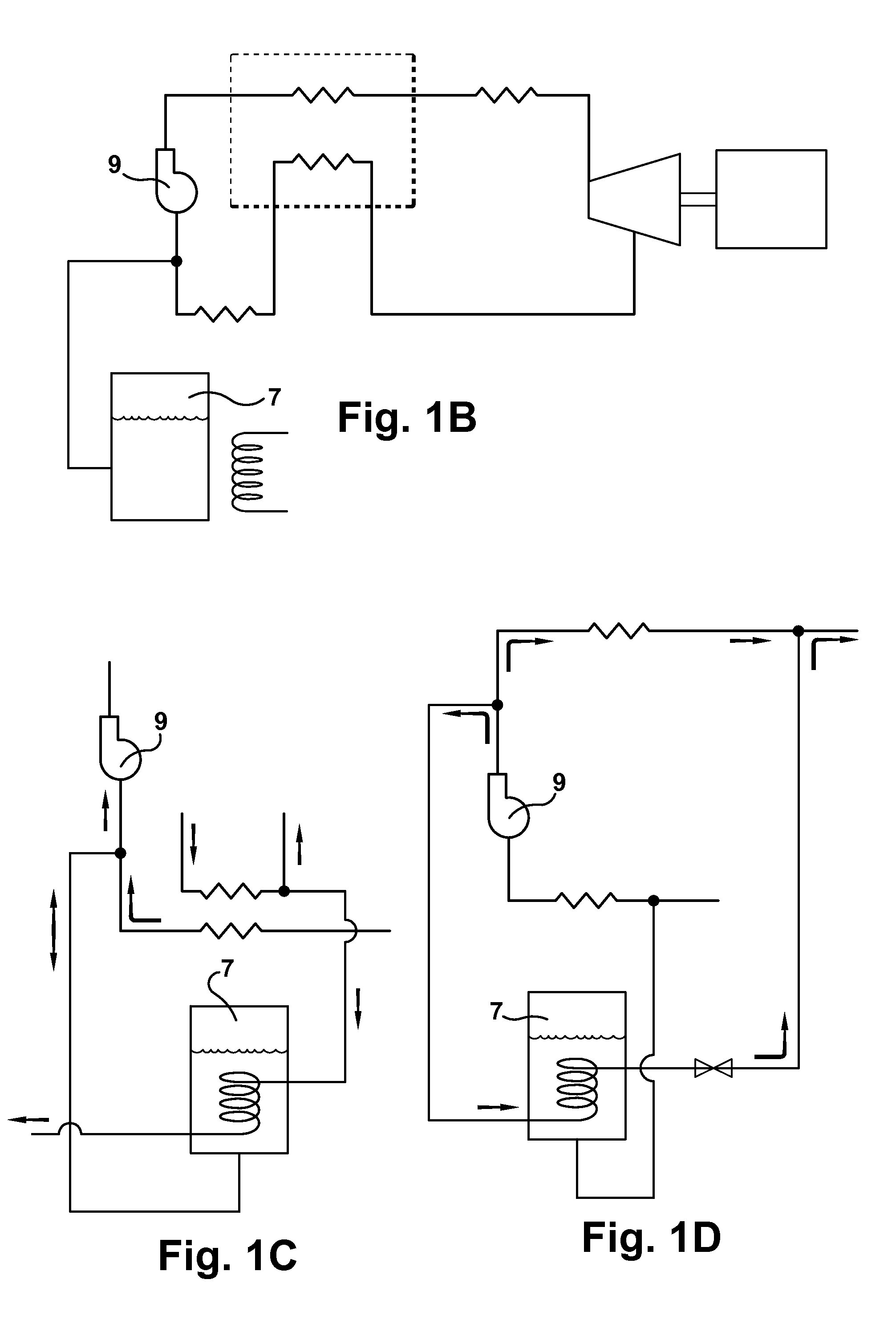
[0017]The inventive heat engine 100 (also referred to herein in the alternative as a “thermal engine”, “power generation device”, “waste heat recovery system” and “heat recovery system”, “heat to electricity system”) of the present disclosure utilizes a thermodynamic cycle which has elements of the Rankine thermodynamic cycle in combination with selected working fluid(s), such as carbon dioxide, to produce power from a wide range of thermal sources. By “thermal engine” or “heat engine” what is generally referred to is the equipment set that executes the thermodynamic cycle described herein; by “heat recovery system” what is generally referred to is the thermal engine in cooperation with other equipment to deliver heat (from any source) to and remove heat from the inventive thermal engine.

[0018]The thermodynamic cycle executed by the heat engine 100 is described with reference to a pressure-enthalpy diagram for a selected working fluid, FIG. 2. The thermodynamic cycle is designed to ...


PUM


Abstract

A waste heat recovery system, method and device executes a thermodynamic cycle using a working fluid in a working fluid circuit which has a high pressure side and a low pressure side. Components of the system in the working fluid circuit include a waste heat exchanger in thermal communication with a waste heat source also connected to the working fluid circuit, whereby thermal energy is transferred from the waste heat source to the working fluid in the working fluid circuit, an expander located between the high pressure side and the low pressure side of the working fluid circuit, the expander operative to convert a pressure / enthalpy drop in the working fluid to mechanical energy, a recuperator in the working fluid circuit operative to transfer thermal energy between the high pressure side and the low pressure side of the working fluid circuit, a cooler in thermal communication with the low pressure side of the working fluid circuit operative to control temperature of the working fluid in the low side of the working fluid circuit, a pump in the working fluid circuit and connected to the low pressure side and to the high pressure side of the working fluid circuit and operative to move the working fluid through the working fluid circuit, and a mass management system connected to the working fluid circuit, the mass management system, method and device having a working fluid vessel connected to the low pressure side of the working fluid circuit and configured to passively control an amount of working fluid mass in the working fluid circuit.

Description

RELATED APPLICATIONS[0001]This application is a conversion of U.S. Provisional patent application No. 61 / 243,200, filed Sep. 17, 2009.FIELD OF THE INVENTION[0002]The present invention is in the field of thermodynamics and is more specifically directed to a heat engine and a related heat to electricity system that utilizes the Rankine thermodynamic cycle in combination with selected working fluids to produce power from a wide range of thermal sources.BACKGROUND OF THE INVENTION[0003]Heat is often created as a byproduct of industrial processes where flowing streams of liquids, solids or gasses that contain heat must be exhausted into the environment or removed in some way in an effort to maintain the operating temperatures of the industrial process equipment. Sometimes the industrial process can use heat exchanger devices to capture the heat and recycle it back into the process via other process streams. Other times it is not feasible to capture and recycle this heat because it is eit...

Claims


Application Information

Patent Timeline
Patent Type & Authority Applications(United States)
IPC IPC(8): F01K25/08F01K13/00F01K19/00
CPCF01K3/185F01K25/103F01K7/165Y02T10/16F01K3/186F24H2240/12Y02T10/12
Inventor HELD, TIMOTHY J.HOSTLER, STEPHENMILLER, JASON D.HUME, BRIAN F.
Owner ECHOGEN POWER SYST
Why Eureka
Try Eureka